MCU with low power mode of operation

a microcontroller and low power technology, applied in pulse generators, instruments, pulse techniques, etc., can solve problems such as leakage current increase, leakage of transistors, and inability to achieve not insignificant current draw

Active Publication Date: 2007-07-19
SILICON LAB INC
View PDF6 Cites 7 Cited by
  • Summary
  • Abstract
  • Description
  • Claims
  • Application Information

AI Technical Summary

Benefits of technology

[0006] The present invention disclosed herein comprises, in one aspect thereof, a low power system for working in conjunction with a digital circuit that is disposed between positive and negative terminals. The system includes an internal voltage generator for increasing, for at least a first portion of the digital circuit, a voltage difference between the at least a first portion of the digital circuit and the voltage on at least one of the positive and negative terminals during a low power mode of operation. This allows the voltage across the at least first portion of the digital circuit to be less than the full voltage across the positive and negative terminals.

Problems solved by technology

However, in this mode of operation, there is still some inherent leakage associated with the transistors.
As the dimensions of the transistors are reduced with advancing technology, this leakage current increases.
Thus, even though the clock is suspended, there is still the possibility of a not insignificant current draw occurring due to the leakage through the transistors that are turned off.

Method used


Image

  • MCU with low power mode of operation
  • MCU with low power mode of operation
  • MCU with low power mode of operation

Examples


Embodiment Construction

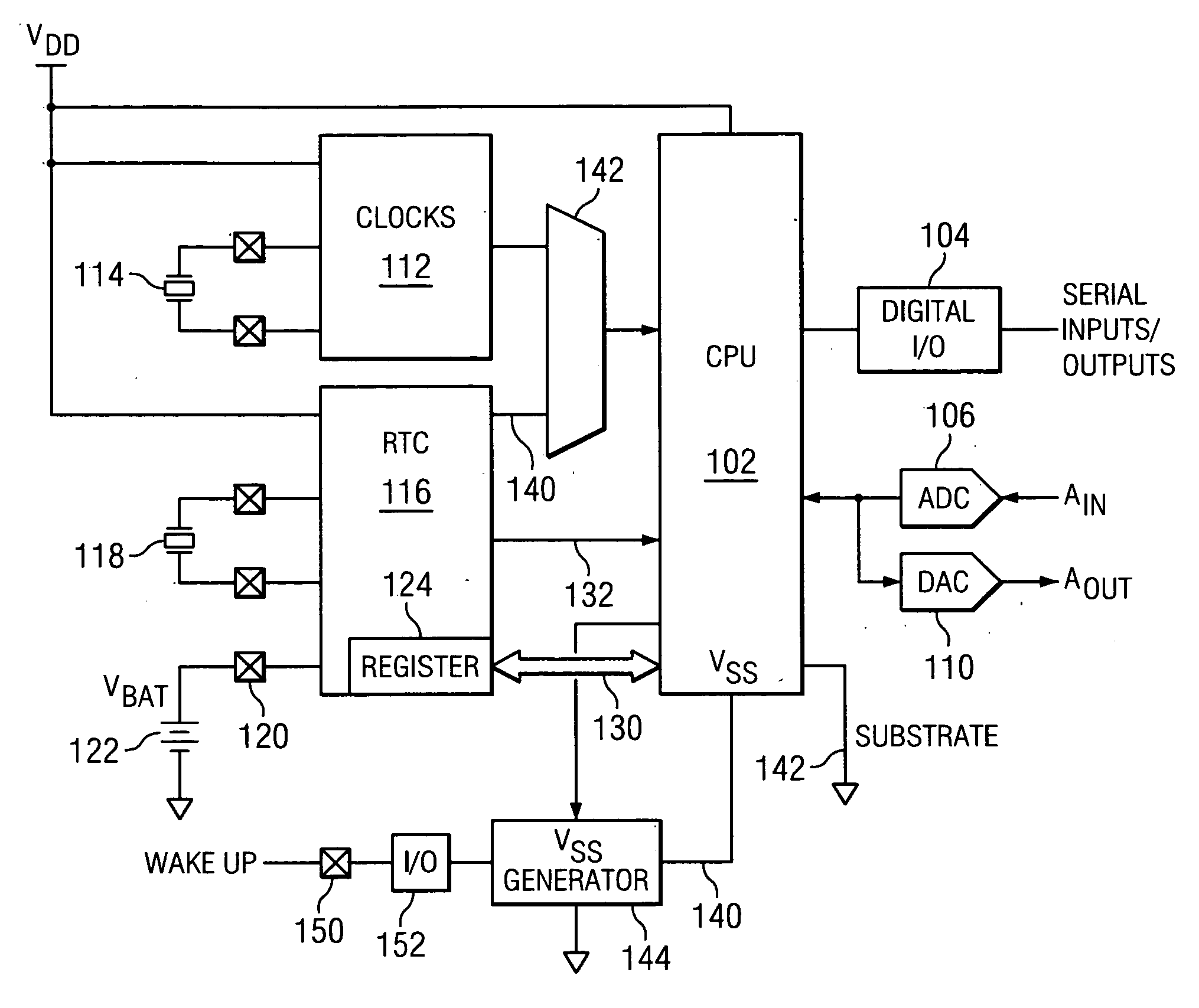
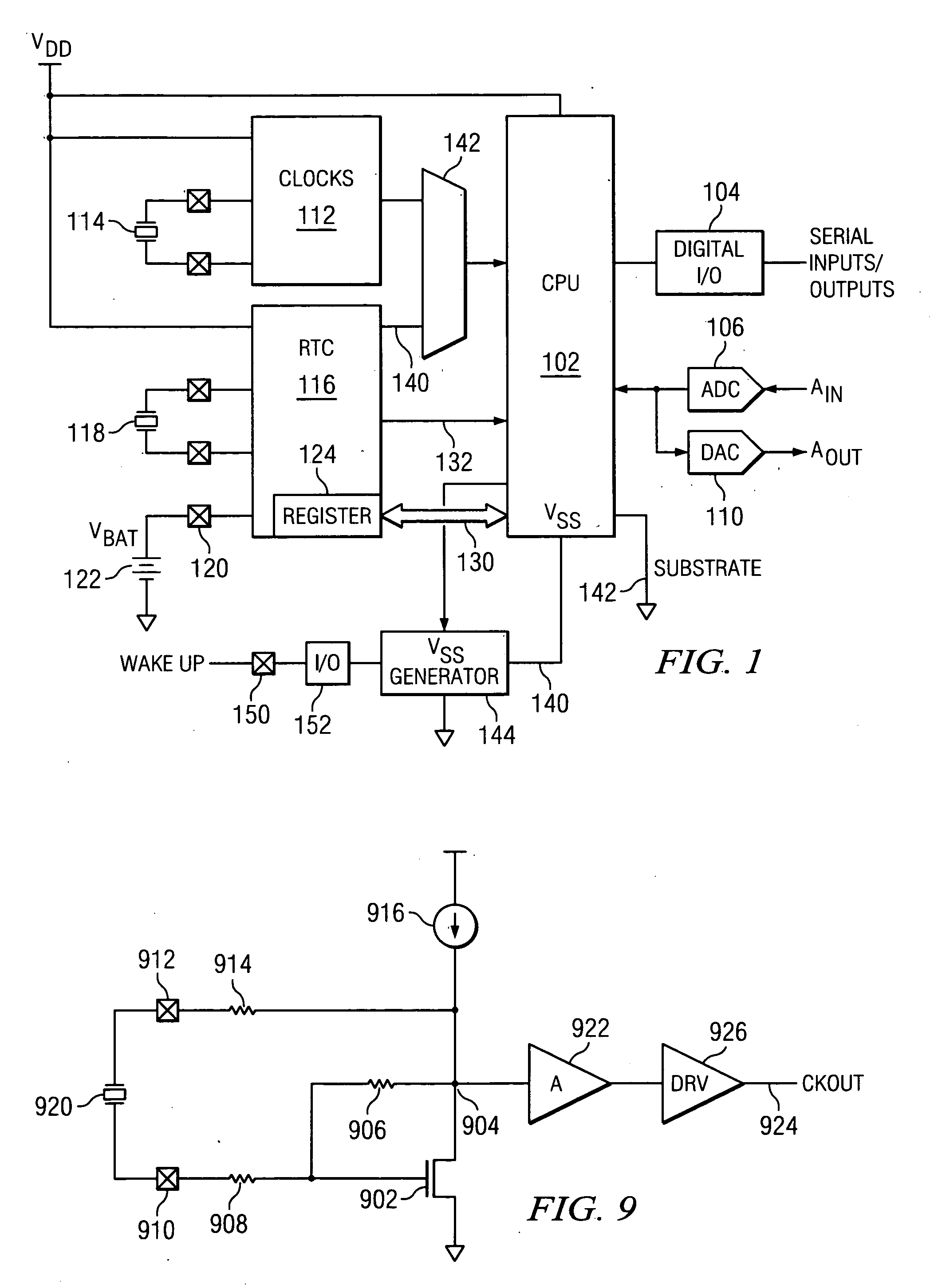
[0029] Referring now to FIG. 1, there is illustrated a block diagram of a processor-based system that drives the mixed signal technologies that include as a part thereof, a digital section including a central processing unit (CPU) 102 and a digital I / O section 104 that is operable to interface with various serial inputs and outputs. The system also includes the analog section which provides for an analog-to-digital converter (ADC) 106 that is operable to receive one or more analog inputs and also provides a digital-to-analog converter (DAC) 110 for allowing digital information from the CPU 102 to be converted to analog output information. The operation of the CPU 102 is controlled by various clocks 112 in a primary oscillator section. These are the operational clocks that control the overall operation of the MCU. In one mode, they will be interfaced with a crystal 114 for precision operation thereof. However, as will be described herein below, a precision internal non-crystal based ...


PUM


Abstract

A low power system is disclosed for working in conjunction with a digital circuit that is disposed between positive and negative terminals. The system includes an internal voltage generator for increasing, for at least a first portion of the digital circuit, a voltage difference between the at least a first portion of the digital circuit and the voltage on at least one of the positive and negative terminals during a low power mode of operation. This allows the voltage across the at least first portion of the digital circuit to be less than the full voltage across the positive and negative terminals.

Description

TECHNICAL FIELD OF THE INVENTION [0001] The present invention pertains in general to microcontroller units (MCUS) and, more particularly, to the power control aspects thereof when placed in a sleep mode of operation. CROSS-REFERENCE TO RELATED APPLICATIONS [0002] N / A BACKGROUND OF THE INVENTION [0003] Microcontroller units (MCU) provide a processor based mixed-signal application integrated circuit that is typically referred to as a system on a chip (SOC). Typically, a processor is provided of the 8051 type, a conventional processor, with memory such as Flash. Data converters are provided for interfacing with the analog domain so as to allow analog data to be collected from various types of sensors. There are also provided various oscillators and the such on the integrated circuit. These SOC integrated circuits are typically directed toward instrumentation type applications that requires interface with sensors and the such, and which can provide some processing of the information fro...

Claims


Application Information

Patent Timeline
Patent Type & Authority Applications(United States)
IPC IPC(8): G06F1/00
CPCG06F1/3203G06F1/324G06F1/3296Y02B60/1285H02M3/156H03K3/3545Y02B60/1217H02M1/36Y02D10/00
Inventor LEUNG, KA Y.
Owner SILICON LAB INC
Why Eureka
Try Eureka