Vehicle integrated control system

a control system and vehicle technology, applied in the field of vehicle integrated control system, can solve the problems of mutual interference, inability to produce independent effects of each of the different types of motion control devices, and the organization of the interaction and coordination between respective motion control devices is difficult, so as to prevent the vehicle from sliding and be convenient to configur

Inactive Publication Date: 2007-07-19
TOYOTA JIDOSHA KK
View PDF4 Cites 22 Cited by
  • Summary
  • Abstract
  • Description
  • Claims
  • Application Information

AI Technical Summary

Benefits of technology

[0014] In view of the foregoing, an object of the present invention is to provide a vehicle integrated control system having the fail-safe faculty improved and capable of readily accommodating addition of a vehicle control function without forming a system that generates a control target of a vehicle at one site.
[0018] In addition to the above-described three subsystems, i.e. the driving system control subsystem, brake system control subsystem and steering system control subsystem in the present invention, a subsystem realizing a DSS is configured so as to operate autonomously and in parallel. In the case where driving request information is transmitted from the subsystem realizing a DSS to the driving system control subsystem in such a configuration, the arbitration unit of the subsystem realizing the DSS executes arbitration for determining as to whether or not the received information from the DSS that is input in addition to the driver's request is to be reflected in the motion control of the vehicle, and to what extent, if to be reflected. As a result of this arbitration, a control target of driving control is generated. Instead of information transmitted from a subsystem to another subsystem to be used at the subsystem of the receiving side for generation of a motion control target, a control target is generated after arbitration by the arbitration unit. Since the subsystems operate autonomously, development is allowed on the basis of each subsystem. Also, when a new driving support function or the like is to be added, the new function can be realized by just adding a subsystem. As a result, there can be provided a vehicle integrated control system having the fail-safe faculty improved and capable of readily accommodating addition of a vehicle control function without forming a system that generates a control target of a vehicle at one site.
[0020] In accordance with the present invention, the driving system control subsystem corresponding to a “running” operation that is the basic operation of the vehicle, the brake system control subsystem corresponding to a “stop” operation, and the steering system control subsystem corresponding to a “turning” operation are configured operable in a manner autonomous and parallel to each other. Additionally, in the case where a driving support system (for example, DSS) of a high level is to be realized, a high level driving support subsystem realizing driving support of a high level is configured operable in a manner autonomous and in parallel, in addition to the driving system control subsystem, brake system control subsystem and steering system control subsystem set forth above. When driving request information is transmitted from the high level driving support subsystem to the driving system control subsystem in such a configuration, the arbitration unit of the high level driving support subsystem executes arbitration for determining as to whether information received from the high level driving support system that is input in addition to the driver's request is to be reflected in the motion control of the vehicle, and to what extent, if to be reflected. As a result of the arbitration, a control target of driving control is generated. Instead of the information transmitted from a subsystem to another subsystem to be used at the subsystem of the receiving side for generation of a target of motion control, a control target is generated after arbitration by the arbitration unit. Since the subsystem operates autonomously, development on the basis of each subsystem is allowed. Also, when a new function or the like is to be added, the new function can be realized by just adding a subsystem. In such a case, a subsystem can be readily added by connecting the subsystems with each other through a communication unit of the subsystem to transmit the required information. Even in the case where one (for example, the high level driving support subsystem) becomes inoperative, the basic operation of the vehicle can be maintained as long as the other three subsystems (driving system control subsystem, brake system control subsystem, and steering system control subsystem) are operating since the subsystems operate autonomously and parallel to each other. As a result, there can be provided a vehicle integrated control system having the fail-safe faculty improved and capable of readily accommodating addition of a vehicle control function without forming a system that generates a control target of a vehicle at one site.
[0030] In accordance with the present invention, an automatic cruise subsystem is added, in addition to the three basic subsystems (drive system control subsystem, brake system control subsystem and steering system control subsystem). Since the three basic subsystems as well as the automatic cruise subsystem operate autonomously and in parallel, development is allowed independently, and a function can be added readily. Such an added function facilitates modification of the contents for each type of a vehicle. The pseudo automatic cruise function includes functions in conformance with automatic cruising such as the cruise control function, lane keep assist function, and the like.
[0032] In accordance with the present invention, the state of behavior of the vehicle is sensed through various sensors equipped in the vehicle. For example, the state of behavior of the vehicle includes the acceleration in the longitudinal direction or lateral direction of the vehicle. When the tendency of slippage of the vehicle is sensed by the low road friction coefficient, the dynamic stabilization subsystem generates information related a control target value to prevent slippage of the vehicle. Upon reception of this generated information at the driving system control subsystem, the arbitration unit gives priority and employs the received information instead of the level of the accelerator pedal manipulated by the driver. Therefore, a control system for stabilization of a vehicle can be readily configured as compared to the manipulation by the driver.

Problems solved by technology

The effect produced by each of the different types of motion control devices may not always emerge in a manner independent of each other at the vehicle.
There is a possibility of mutual interference.
In the case of developing a plurality of types of motion control devices in the aforesaid manner, organization of the interaction and coordination between respective motion control devices requires much time and effort.
This scheme involves the problem of how the contention among the plurality of motion control devices, when required to operate the same actuator at the same time, is to be resolved.
In the above-described case where the interaction and coordination among a plurality of motion control devices are to be organized in a supplemental or additional manner after the motion control devices are developed independently of each other, it is difficult to solve the problem set forth above proficiently.
The electronic control system for a vehicle disclosed in Document 1 is disadvantageous in that the entire controllability of the vehicle is degraded when in the event of system failure at the upper hierarchical level since the entire system employs a hierarchy structure.
Although this integrated type vehicle motion control device is advantageous from the standpoint of concurrent processing of development by virtue of independency thereof, the issue of depending upon the basic concept of hierarchy is not yet resolved.

Method used


Image

  • Vehicle integrated control system
  • Vehicle integrated control system
  • Vehicle integrated control system

Examples


first embodiment

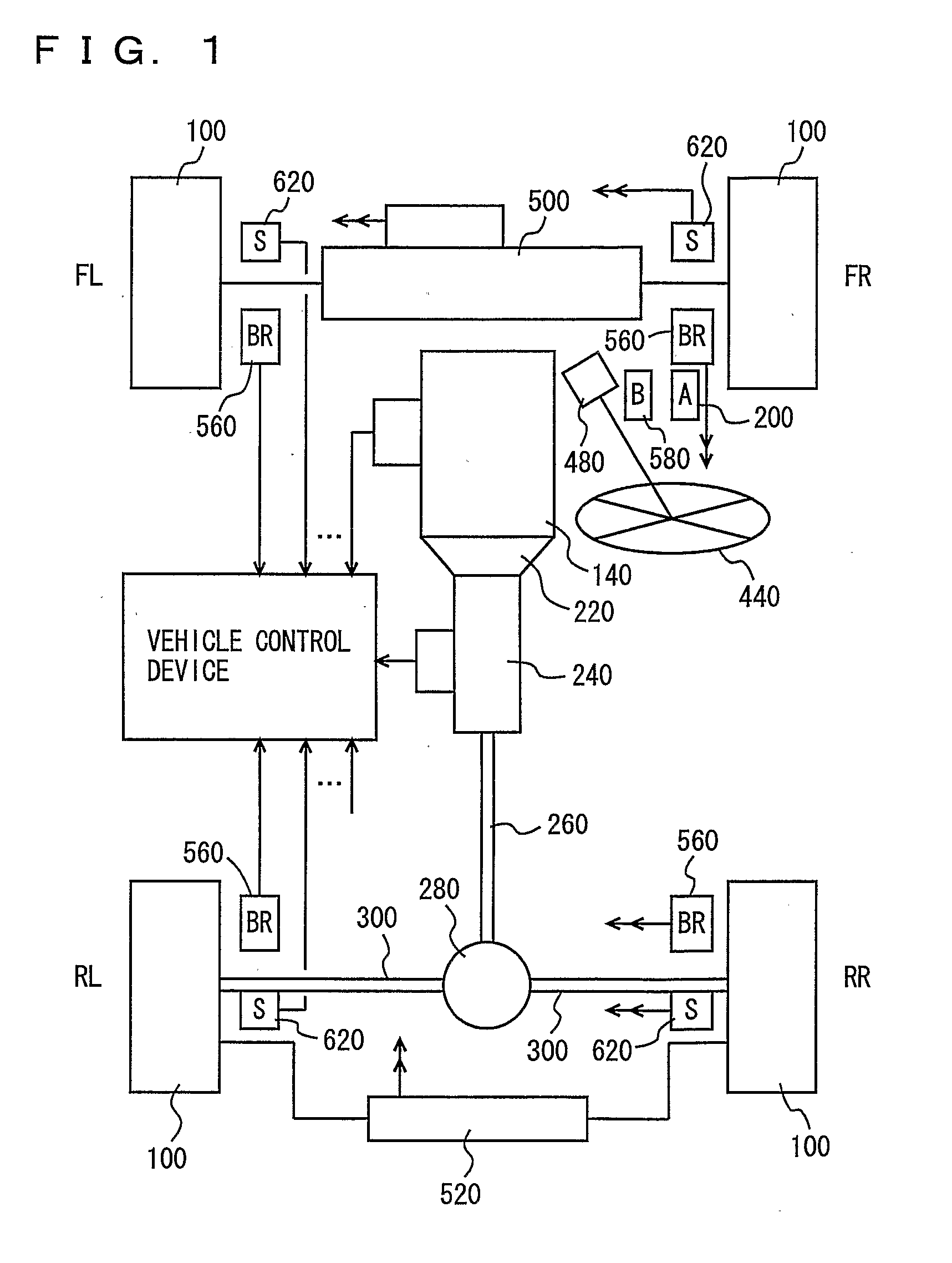
[0042] Referring to the block diagram of FIG. 1, a vehicle integrated control system according to an embodiment of the present invention has an internal combustion engine incorporated in a vehicle as a driving power source. The driving power source is not restricted to an internal combustion engine, and may be an electric motor alone, or a combination of an engine and an electric motor. The power source of the electric motor may be a secondary battery or a cell.

[0043] The vehicle includes wheels 100 at the front and back of respective sides. In FIG. 1, “FL” denotes a front-left wheel, “FR” denotes a front-right wheel, “RL” denotes a left-rear wheel, and “RR” denotes a rear-right wheel.

[0044] The vehicle incorporates an engine 140 as a power source. The operating state of engine 140 is electrically controlled in accordance with the amount or level by which the accelerator pedal (which is one example of a member operated by the driver related to the vehicle drive) is manipulated by ...

second embodiment

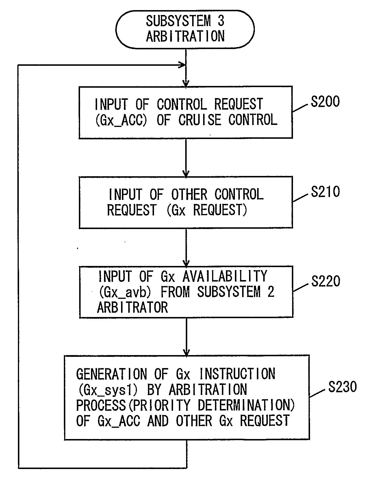
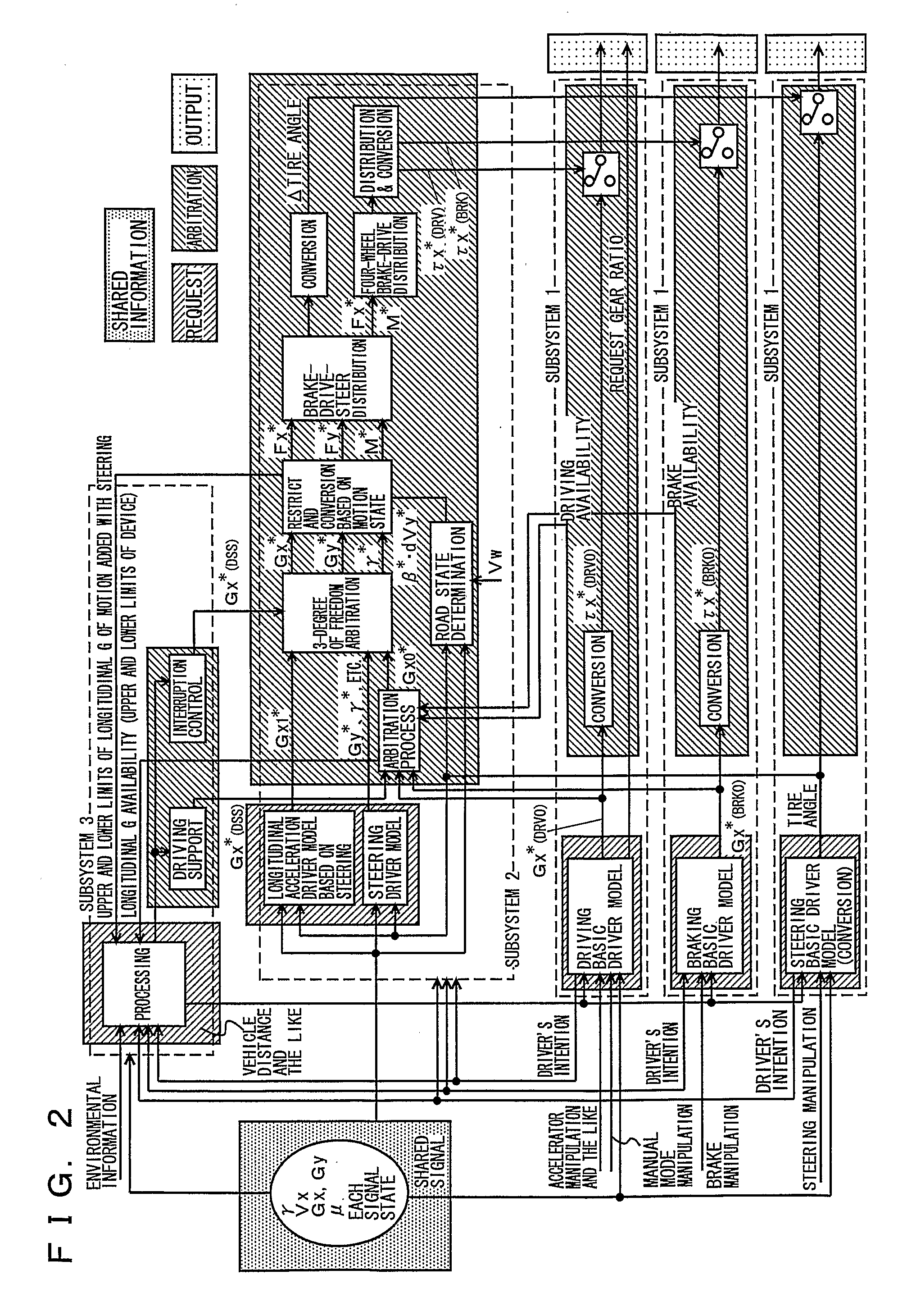
[0119] A vehicle integrated control system according to a second embodiment of the present invention will be described hereinafter with reference to FIG. 13 corresponding to a control configuration. This FIG. 13 corresponds to FIG. 2.

[0120] As shown in FIG. 13, the vehicle integrated control system of the second embodiment is formed of three basic control units, i.e. a main control system (1) as the driving system control unit, a main control system (2) as the brake system control unit, and a main control system (3) as the steering system control unit.

[0121] At main control system (1) identified as the driving system control unit, a control target of the driving system corresponding to accelerator pedal manipulation is generated using the driving basic driver model, based on the accelerator pedal manipulation that is the sensed request of the driver, whereby the actuator is controlled. At main control system (1), the input signal from the sensor to sense the accelerator pedal open...


PUM


Abstract

An integrated control system includes subsystem with a driving system control subsystem controlling a driving system, a brake system control subsystem controlling a brake system, and a steering system control subsystem controlling a steering system, a subsystem stabilizing a current dynamic state of the vehicle, a subsystem realizing a driving support function such as automatic cruising, and a storage unit for storing shared signals. Each subsystem includes a request unit, an arbitration unit, and an output unit.

Description

TECHNICAL FIELD [0001] The present invention relates to a system controlling a plurality of actuators incorporated in a vehicle, and more particularly, a system controlling in an integrated manner a plurality of actuators with the possibility of mutual interference. BACKGROUND ART [0002] There has been an increasing trend in recent years towards incorporating many types of motion control devices in the same vehicle to control the motion of the vehicle. The effect produced by each of the different types of motion control devices may not always emerge in a manner independent of each other at the vehicle. There is a possibility of mutual interference. It is therefore important to sufficiently organize the interaction and coordination between respective motion control devices in developing a vehicle that incorporates a plurality of types of motion control devices. [0003] For example, when it is required to incorporate a plurality of types of motion control devices in one vehicle in the ...

Claims


Application Information

Patent Timeline
Patent Type & Authority Applications(United States)
IPC IPC(8): G06F9/45B60R16/02B60T8/1755B60T8/58B60W10/00B60W10/04B60W10/06B60W10/18B60W10/192B60W10/20B60W50/00B60W50/04B62D6/00B62D117/00
CPCB60K41/282B60K2741/283B60W10/04B60W10/18B60W50/06B60W40/10B60W50/02B60W50/04B60W10/20B60W2520/10B60W2520/105B60W2520/14B60W2540/10B60W2540/12B60W2540/18B60W2710/18B60W2710/20B60R16/0231B60W30/00
Inventor HASHIMOTO, YOSHIYUKIHIROSE, MASANORIOTAKE, HIROTADATAKAMATSU, HIDEKI
Owner TOYOTA JIDOSHA KK
Why Eureka
Try Eureka