[0021] Still other objects and advantages of the present invention will become apparent from the following description of the preferred embodiments.
DETAILED DESCRIPTION OF THE PREFERRED EMBODIMENTS
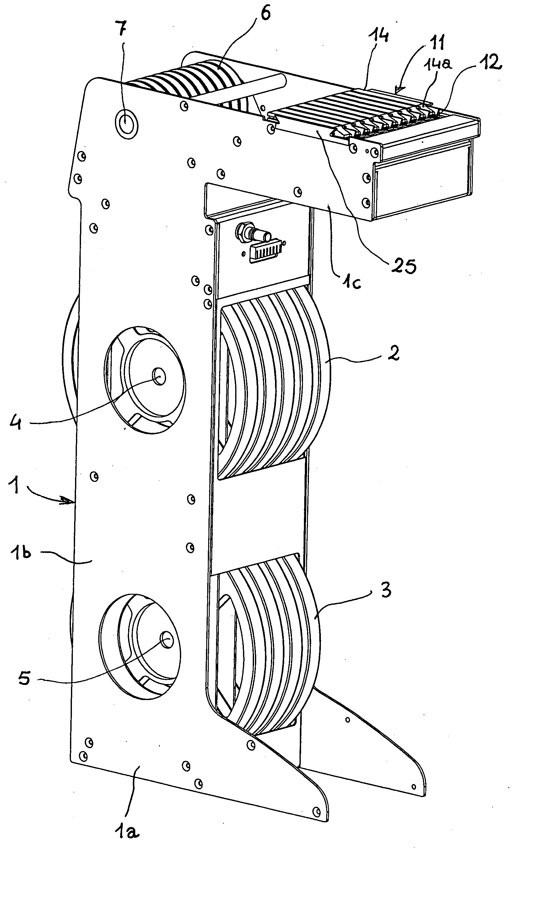
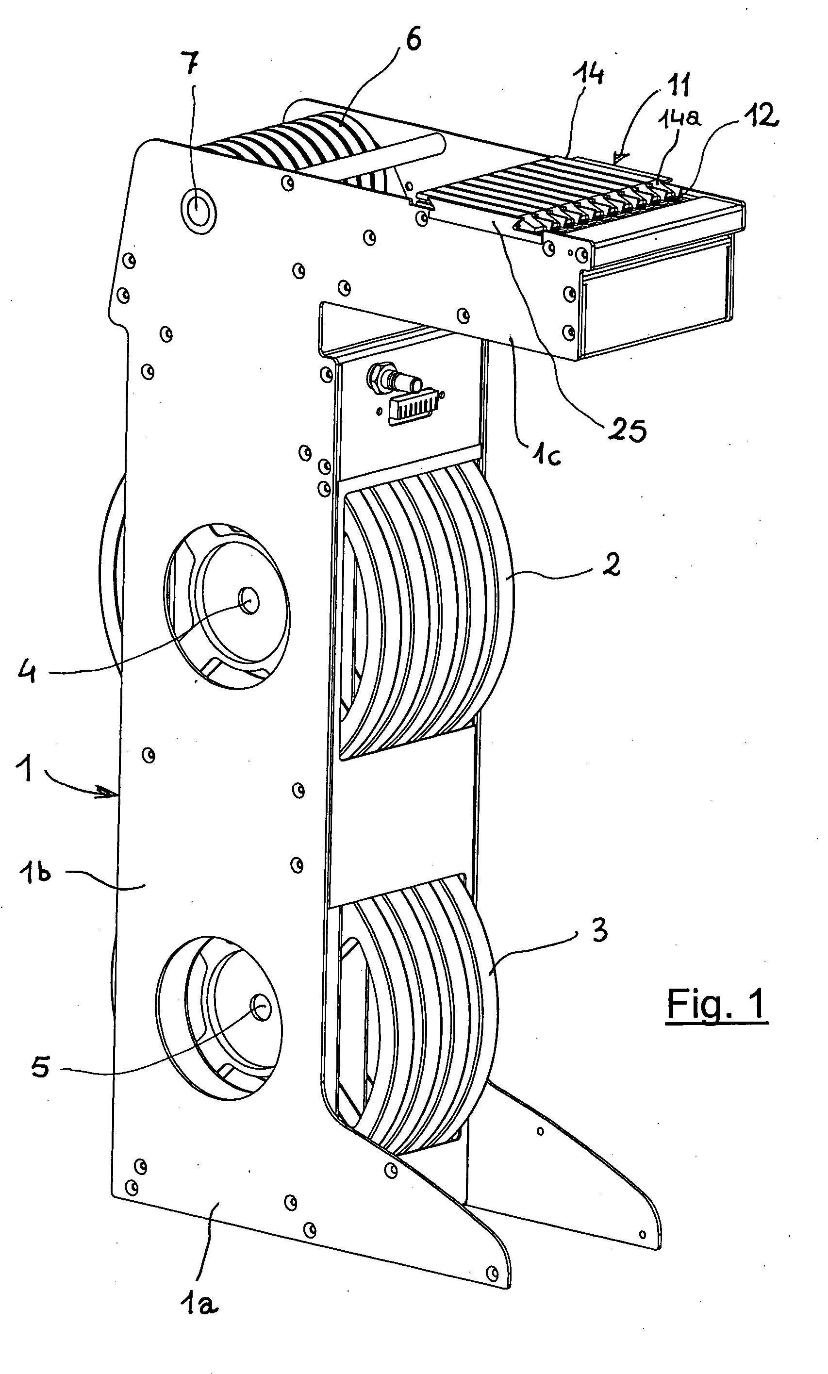
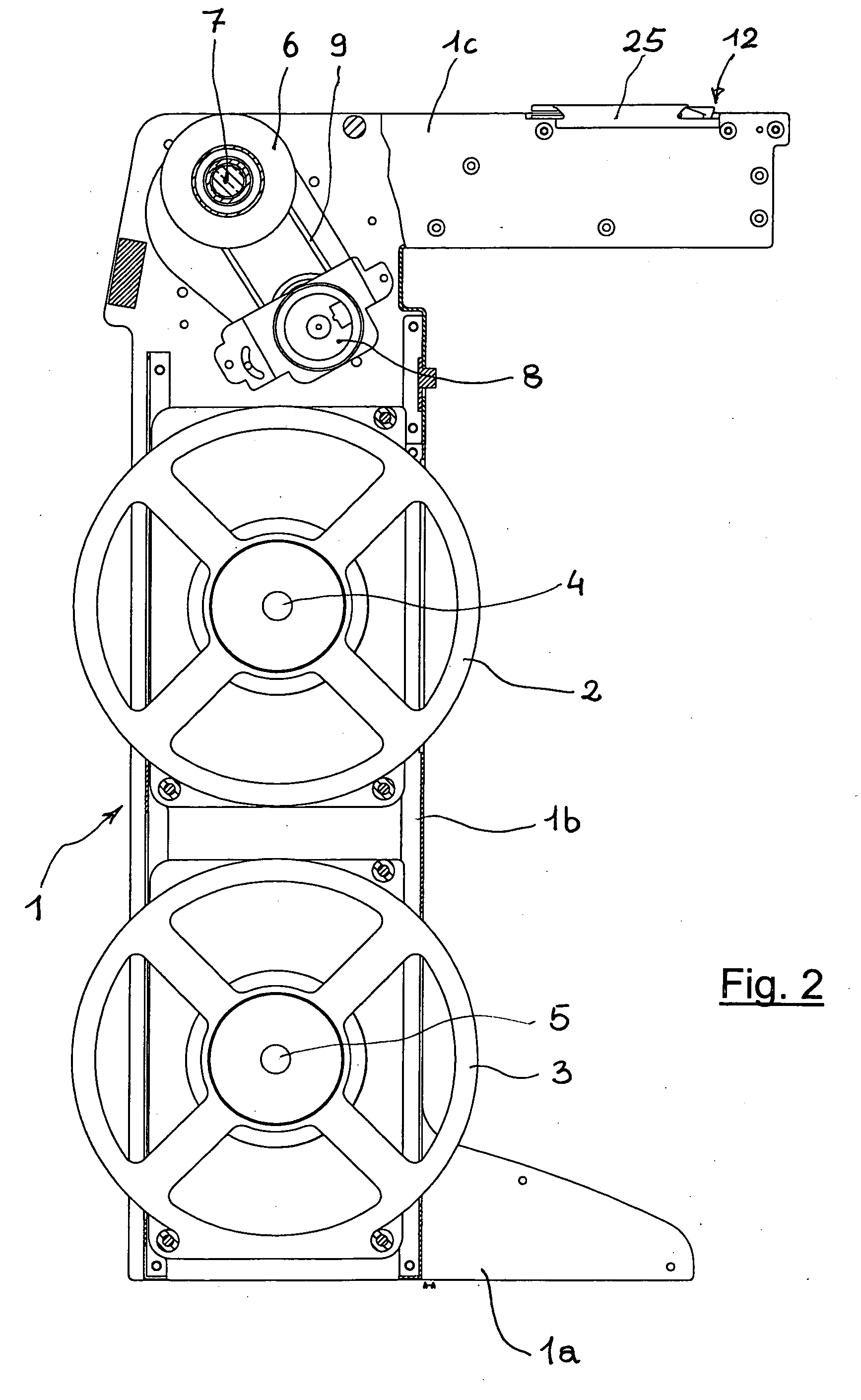
[0022] Referring now to the drawings and, more particularly, to FIGS. 1-6, there is shown generally a specific, illustrative linear multiple feeder for automatic surface-mounting device (SMD) positioning machines, according to various aspects of the present invention. In one embodiment, illustrated in FIGS. 1-3, the feeder has a relatively rigid, box-like frame comprising a base portion la, an upright portion 1b rising from the base portion, and a top portion 1c extending generally horizontally from a free end of the upright portion. Inside upright portion 1b, reels 2, 3 are desirably mounted revolvingly on respective spindles 4, 5 supported on either side, preferably at two different heights, by the upright portion. It is preferred that the reels be staggered relatively vertically so as to avoid any interference between tape(s) containing the SMD being unwound therefrom. At an upper end of upright portion 1b, generally at the same height as top portion 1c, a shaft 7 is provided on which a battery of driving wheels 6 is integrally mounted for retrieving a film coating detached from the tape containing the SMD. The shaft is connected to a geared motor 8 by a traditional pulley transmission system (not shown) having a geared wheel 9, shown in FIG. 2.
[0023] With reference also to FIG. 5, the top portion 1c comprises a horizontal bed 10 containing a plurality of longitudinal lanes 11, lying parallel to one another for the controlled feeding of the tape carrying the components towards a pickup area generically indicated by the numeral 12, situated at the free end of the top portion 1c. Inside the latter, underneath the bed 10, there is a device for feeding the tape forward, indicated generically by the reference number 13. The lanes also contain respective film separators 14 consisting of suitably shaped bars, described in more detail later on.
[0024] With particular reference to FIGS. 3 and 4, the delivery device 13 comprises an actuator 15, which is pneumatic in the present embodiment of the invention, solidly attached to the bed 10 with a mobile stem 16 connected by means of a bracket 20 to a transverse carriage 17 and to a block 21 sliding inside a guide (not shown) that is integral to the bed 10. The carriage is longitudinally movable between two stops 18 and 19.
[0025] Inside the carriage 17, there is a row of pins 22 into a crosswise arrangement. The pins 22 have a body 22a that fits inside a seat 23 in the carriage 17 and they are designed so that their pointed end projects from a head 17a extending crosswise over the carriage 17. The pins 22 are arranged vertically with their pointed ends facing the lanes 11 and they are axially mobile within the carriage 17 so that they can selectively engage in or be disengaged from the guide holes aligned along at least one side of the tape carrying the SMD, a length of which (indicated by the letter N) is shown in FIG. 5. The axial movement of the pins 22 is controlled by pneumatic actuators 24.
[0026] The sliding lanes 11 have side walls 25 between which the film separators 14 are installed. As shown in detail in FIG. 6, the walls 25 frontally (i.e. in the area facing the pickup section 12) present an edge 25a that slopes in the opposite direction with respect to the pickup section 12 and, towards the bottom of the respective lane, against which a blocking pin 26 (that extends across the front end 14a of the separator 14) abuts. The end 14a of the separator 14 is substantially wedge-shaped so as to guide the coating film, which slides over the separator 14, coming up against its end 14a, after it has been detached from the tape carrying the SMD as a result of the tensile stress brought to bear by the respective film rewinding wheel 6 on which it is retrieved.
[0027] The opposite edge 25b of the walls 25 slopes in the opposite direction to edge 25a and serves as a striker for a second transverse pin 27 connected to a spring (not shown) contained longitudinally inside the separator 14.
[0028] The feeder according to the invention functions as explained below.
[0029] In the condition when the feeder is at rest, the tapes containing the SMD are placed inside respective lanes 11 and the protective film, already partly detached from the respective tapes, passes over the separators 14 and is wound around respective film-retrieving driving wheels, which are at a standstill. The carriage 17 is in its withdrawn position up against the rear stop 18, and the pins 22 are each engaged in a hole in the respective tape.
[0030] When a delivery signal is issued, the geared motor 8 turns the film-retrieving driving wheels 6, which draw the coating film taut. The tension on the film comes to bear on the ends 14a of the separators 14, which are thus drawn back. Given the restraining effect of the blocking pins 26 abutting against the sloping edges 25a, which makes the pins 26 slide along said edges, the separators 14 re pushed downwards and come to rest on the tapes, holding them pressed against the bottom of their respective lanes 11. Meanwhile, the tape-entraining pins 22 are withdrawn inside the carriage 17 to disengage them from the respective tapes with the exception of those engaged in the tapes selected for delivery. The carriage 17 advances to the front stop 19 entraining the tapes in which the selected pins 22 have remained engaged, while the drive wheels 6 continue ot keep the film pull taut.
[0031] Once the SMD have been collected, the tape-entraining pins 22 engaged in the selected tapes drop back into the carriage 17, thus becoming disengaged from the tape, and the carriage returns to the opposite end of its stroke 18, while the drive wheels 6 ensure the retrieval of the film detached from the selected tapes as a result of the delivery stroke. Then all the tape-entraining pins 22 reemerge, hooking up the tapes again, while the film retrieving drive wheels 6 stop and the feeder returns to its resting condition, ready for a new feeding cycle.
[0032] Thus, the tapes that do not need to move forward are kept at a standstill by the separators 14 due to the effect of the tension on the films, which would normally tend to displace them. This ensures the utmost precision and repeatability of the delivery cycles because the tapes that do not need to advance are hold in place, ensuring that there is no, even minimal movement on their part that could prevent the subsequent engagement of the tape-entraining pins in the holes in the tapes when the carriage is drawn back.
[0033] The second pin 27 exerts an auxiliary tensile action in the same direction as the one brought to bear by the film-retrieving wheels 6. This auxiliary action is useful both to reinforce the downward thrust towards the bottom of the lanes 11, which helps to hold the tapes fast therein and to compensate for any (ultimately unavoidable) discrepancy in the turning speeds of the film-retrieving wheels 6. Finally, the combined and opposing action of the transverse pins 26 and 27 ensures the stable positioning of the separators 14 inside their respective lanes 11, preventing their accidental or unwanted displacement.
[0034] It should be noted, moreover, that the provision of a movement of the carriage 17 with a fixed stroke between the two stops 18 and 19 contributes simply and reliably to ensuring an excellent repeatability of exposure of the components. In addition, the assembly of the tapes on the feeder is straightforward and practical because the film separators are simply rested on the tapes and can consequently be promptly removed from their respective lanes, to allow for the positioning of the tapes, and then put back in place.
[0035] Various modifications and alterations may be appreciated based on a review of this disclosure. These changes and additions are intended to be within the scope and spirit of the invention as defined by the following claims.