

Heat-resistant resin laminated film, multilayer film with metal layer including same and semiconductor device
a technology of laminated film and heat-resistant resin, which is applied in the direction of synthetic resin layered products, applications, other domestic articles, etc., can solve the problems of poor heat resistance, insufficient utilization of excellent characteristics of polyimide films, and wiring cutting, and achieve high-reliability semiconductor devices.
- Summary
- Abstract
- Description
- Claims
- Application Information
AI Technical Summary
Benefits of technology
Problems solved by technology
Method used
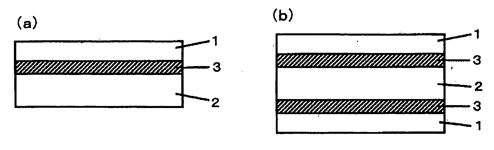
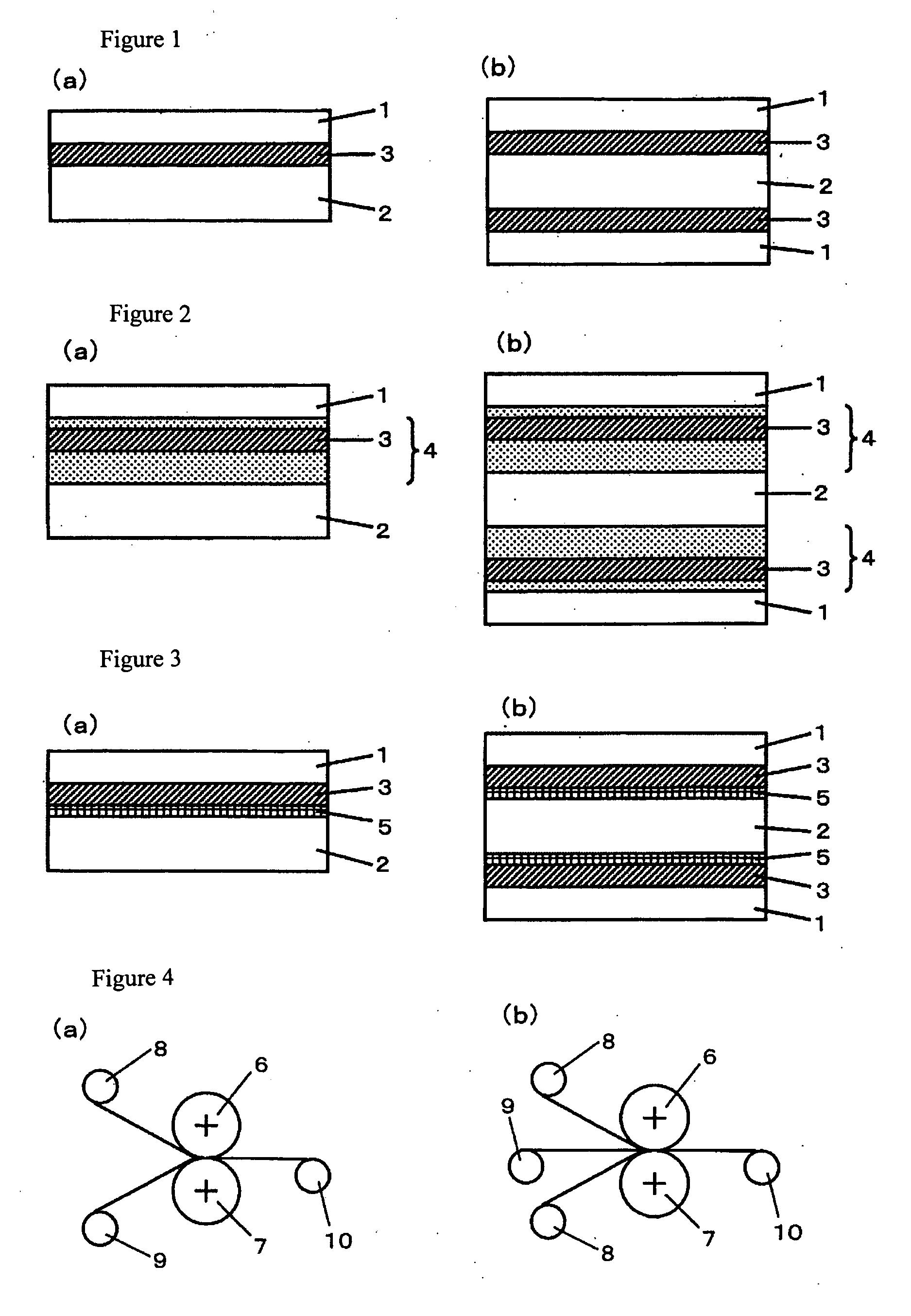
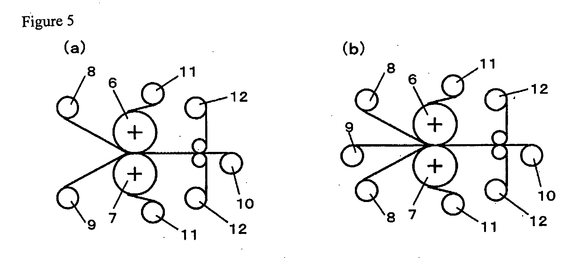
Image

Examples
production example 1
[0130] To a reaction kettle equipped with a thermometer, dry nitrogen inlet, heating and cooling systems using hot and cooling water, and a stirrer, 12.43 g (0.05 mol) of SiDA, 50.05 g (0.25 mol) of DAE and 75.67 g (0.7 mol) of PDA were fed together with 2450 g of NMP. After dissolving the materials, 294.2 g (1 mol) of BPDA was added, and the resulting mixture was allowed to react at 70° C. for 6 hours to obtain a polyamic acid resin solution (PA1) having a concentration of 15% by weight. The resin obtained by imidation of the polyamic acid resin solution (PA1) had a coefficient of linear expansion of 20 ppm / ° C., a percentage of water absorption of 1.1 wt % and a glass transition temperature of 283° C.
production examples 2-7
[0131] The same operations as in Production Example 1 were repeated except that the types and the fed amounts of the acid dianhydride and diamine were changed as shown in Table 1 to obtain polyamic acid resin solutions (PA2-7) having a concentration of 15% by weight. The coefficients of linear expansion, percentages of water absorption and the glass transition temperatures of the resins obtained by imidizing the polyamic acid resin solutions (PA2-7) are shown in Table 1.
production example 8
[0132] The same operations as in Production Example 1 were repeated except that the types and the fed amounts of the acid dianhydride and diamine were changed as shown in Table 1 to obtain a polyamic acid resin solution (PA8) having a concentration of 15% by weight. The coefficient of linear expansion, percentage of water absorption and the glass transition temperature of the resin obtained by imidizing the polyamic acid resin solution (PA8) are shown in Table 1.
TABLE 1Upper row: Number of moles (mol) / Lower row: Fed amounts (g)TetracarboxylicCoefficientPercentageGlassAcidof Linearof WaterTransitionComponentDiamine ComponentSolventExpansionAbsorptionTemperatureBPDAOPDASiDADAEPDADABAm-TBDMAc(ppm / ° C.)(wt %)(° C.)ProductionPA11.000.050.250.702450201.1283Example 1294.2012.4350.0575.67ProductionPA21.000.400.602488201.6295Example 2294.2080.0864.86ProductionPA31.000.050.350.602907181.2304Example 3294.2012.4370.07136.38ProductionPA41.000.800.202697421.8310Example 4294.20160.1621.62Product...
PUM
| Property | Measurement | Unit |
|---|---|---|
| thickness | aaaaa | aaaaa |
| temperature | aaaaa | aaaaa |
| thickness | aaaaa | aaaaa |
Abstract
Description
Claims
Application Information