Ultrahigh energy short pulse lasers

a high-energy, laser technology, applied in the direction of laser details, basic electric elements, electrical equipment, etc., can solve the problems of inability to easily generate ultra-high-energy short-pulse lasers with ultra-high energy over 10 mj up to 100 mj, limited cpa systems, and technical limitations of ordinary skill in the art, so as to achieve the effect of improving reliability

Active Publication Date: 2007-07-26
POLARONYX
View PDF1 Cites 29 Cited by
  • Summary
  • Abstract
  • Description
  • Claims
  • Application Information

AI Technical Summary

Benefits of technology

[0009] Another aspect of this invention is to implement a new generation of all diode pumped all-solid laser system. This design can be the basis for a novel avenue targeting ultras-high energy short pulse amplifier with unprecedented and dramatically improved reliability, stability and compactness.

Problems solved by technology

Even though current technologies of fiber laser have made significant progress toward achieving a compact and reliable fiber laser system providing high quality output laser with ever increasing output energy, however those of ordinary skill in the art are still confronted with technical limitations and difficulties.
Specifically, in a fiber laser system implemented with the Chirped Pulse Amplification (CPA) for short pulse high power laser amplifier, the CPA systems are still limited by the technical difficulties that a short pulse laser with an ultra-high energy over 10 mJ up to 100 mJ cannot be easily generated.
There are several technical problems that limit the generation of such ultra-high energy lasers.
Under certain average power, it is hard to get very high pulse energy if one keeps such a high repetition rate.
Another technical difficulty of a fiber based laser system with short pulses is the limitations due to the nonlinear effects, such as third order dispersion (TOD) cased in fiber based pulse streching, self-phase modulation (SPM), and stimulated Raman effects (SRS).
This configuration leads to a more complicated system and a higher cost.
Even with the preamplifier with an output of <400 mW, which is mainly limited by single mode pump diode, the average power after the pulse picker is still below 0.5 mW, which requires a delicate and elaborate design for the amplification chain.
However, for the fiber system, the tight confinement of laser light in a small core makes it very hard to achieve high peak power due to nonlinear effects.

Method used


Image

  • Ultrahigh energy short pulse lasers
  • Ultrahigh energy short pulse lasers
  • Ultrahigh energy short pulse lasers

Examples


Embodiment Construction

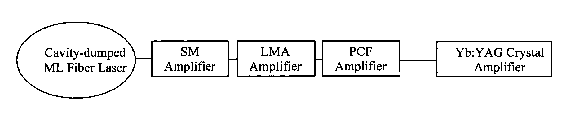
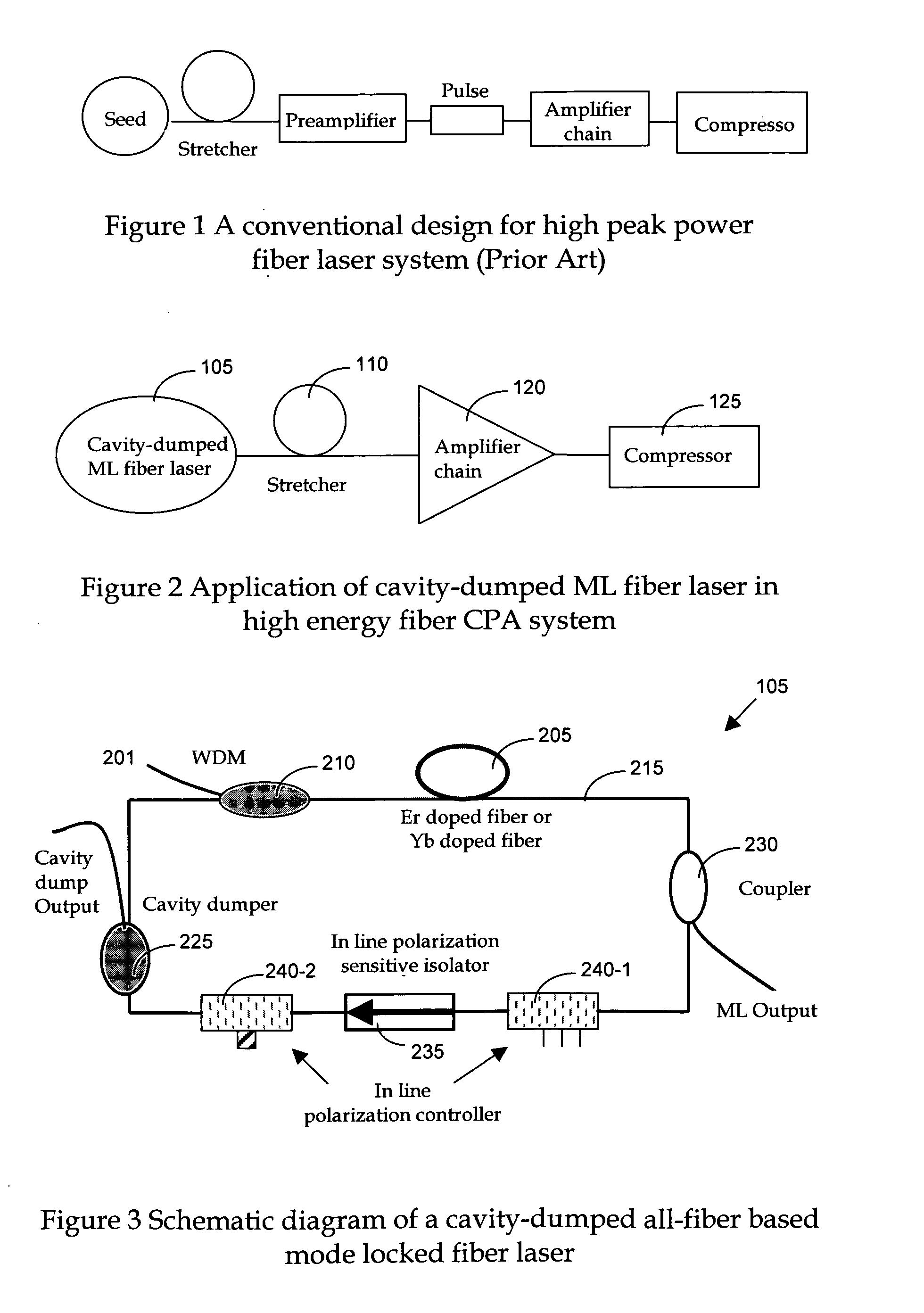
[0022] Referring to FIG. 2 for a schematic diagram of a fiber laser system 100 of this invention that implements a dispersion compensator of this invention. The laser system 100 includes a laser seed 105 as a mode-locked (ML) oscillator that is implemented as a cavity dump ML fiber laser for generating a seed laser for projecting into a laser stretcher 110 to stretch the laser pulse. The stretcher 110 generates laser pulse with stretched pulse width is projected into series of laser amplifiers 120 to amplify the laser into higher energy. The amplified laser is then projected into a pulse compressor 125 to re-compress the pulse width of the laser to output a laser with original pulse width. There is particular advantage to combine the all-fiber based ML fiber laser with cavity dumping in the cavity-dumped ML fiber laser 105. The cavity-dumped ML fiber laser can have more than 1 mW average power with a repetition rate of 10 KHz-100 KHz. Compared to convention laser operating typically...


PUM


Abstract

A Chirped pulse amplification (CPA) fiber laser system. The CPA fiber laser system includes a fiber mode-locking (ML) oscillator implemented as a cavity dumped ML oscillator including a cavity dumper for generating a seed laser at a reduced repetition rate to project to a pulse stretcher for stretching a pulse width of the laser. The CPA fiber laser system further includes a multistage amplifier chain for generating an amplified laser to project to a compressor for compressing the amplified laser. The multistage amplifier chain further includes a hybrid amplifier includes a solid-state amplifier to generate a laser of approximately 1˜10 mJ for a 10-100 KHz repetition rate.

Description

[0001] This Formal Application claims a Priority Date of Oct. 17, 2005 benefited from a Provisional Patent Applications 60 / 727,350, 60 / 727,351, 60 / 730,632, and a Priority Date of Oct. 26, 2005 benefited from Provisional Applications 60 / 730,832 filed by one of the same Applicants of this Application.FIELD OF THE INVENTION [0002] The present invention relates generally to apparatuses and methods for providing laser system. More particularly, this invention relates to a design and system configuration for generating lasers with short pulses at ultra-high energy towards tens of mJ energy level femtosecond fiber lasers by combining a Chirped Pulse Amplification (CPA) fiber laser system with a solid state amplifier. BACKGROUND OF THE INVENTION [0003] Even though current technologies of fiber laser have made significant progress toward achieving a compact and reliable fiber laser system providing high quality output laser with ever increasing output energy, however those of ordinary skill ...

Claims


Application Information

Patent Timeline
Patent Type & Authority Applications(United States)
IPC IPC(8): H01S3/30H01S3/11
CPCH01S3/0057H01S3/05H01S3/067H01S3/06741H01S3/06758H01S3/2375H01S3/115H01S3/117H01S3/1618H01S3/1643H01S3/1103
Inventor LIU, JIANXIA, JIANGFAN
Owner POLARONYX
Why Eureka
Try Eureka