
Vacuum pump

a vacuum pump and vacuum technology, applied in the direction of liquid fuel engines, positive displacement liquid engines, sealing, etc., can solve the problems of reducing the gas affecting the efficiency of the pump, and requiring a large amount of gas separation and recovery, so as to reduce the consumption of seal gas, facilitate gas recovery, and prevent corrosion

Inactive Publication Date: 2007-07-26
FOUND FOR ADVANCEMENT OF INT SCI
View PDF6 Cites 6 Cited by
  • Summary
  • Abstract
  • Description
  • Claims
  • Application Information

AI Technical Summary

Benefits of technology

[0026] According to this invention, it is possible to obtain a vacuum pump comprising shaft seals that largely reduce the consumption amount of seal gas, prevent corrosion due to corrosive gas, facilitate gas recovery, and further ensure smooth operation.
[0027] Further, according to this invention, the smooth operation of a screw pump is enabled and, when the operation is smoothed, the rotation can be faster. When the rotation becomes faster, the pumping speed increases so that the ultimate pressure can be reduced. As a result, the uniform pumping speed can be maintained even over the low inlet pressure region and, hence, in the case of a system formed by connecting vacuum pumps in a plurality of stages, it is possible to omit the pump such as, for example, a turbomolecular pump at the stage prior to the present vacuum pump.

Problems solved by technology

However, since it is not possible to completely prevent leakage of ball bearing oil to the screw (pump) side, in case of being used as a vacuum pump in a processing step (plasma etching, reduced-pressure vapor phase epitaxy) that emits a toxic gas, a corrosive gas, or the like in a depressurized state when, for example, manufacturing semiconductor elements, the gas contacts the ball bearings to corrode the bearings or the oil at the bearing portions flows into the inside of the pump, thereby causing serious failure in the processing step.
Further, there has been a technical problem that reaction product is accumulated on the ball bearings to impede smooth operation.
Further, there has been a big technical problem that since the gas introducing amount is large, a huge cost is required for separating and recovering an expensive gas such as Kr or Xe used in the processing step.

Method used


Image

  • Vacuum pump
  • Vacuum pump
  • Vacuum pump

Examples


embodiment 1

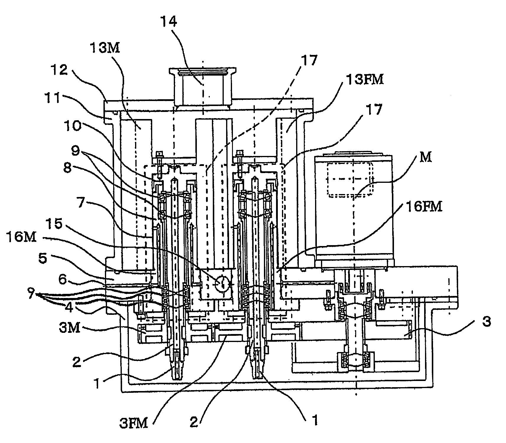
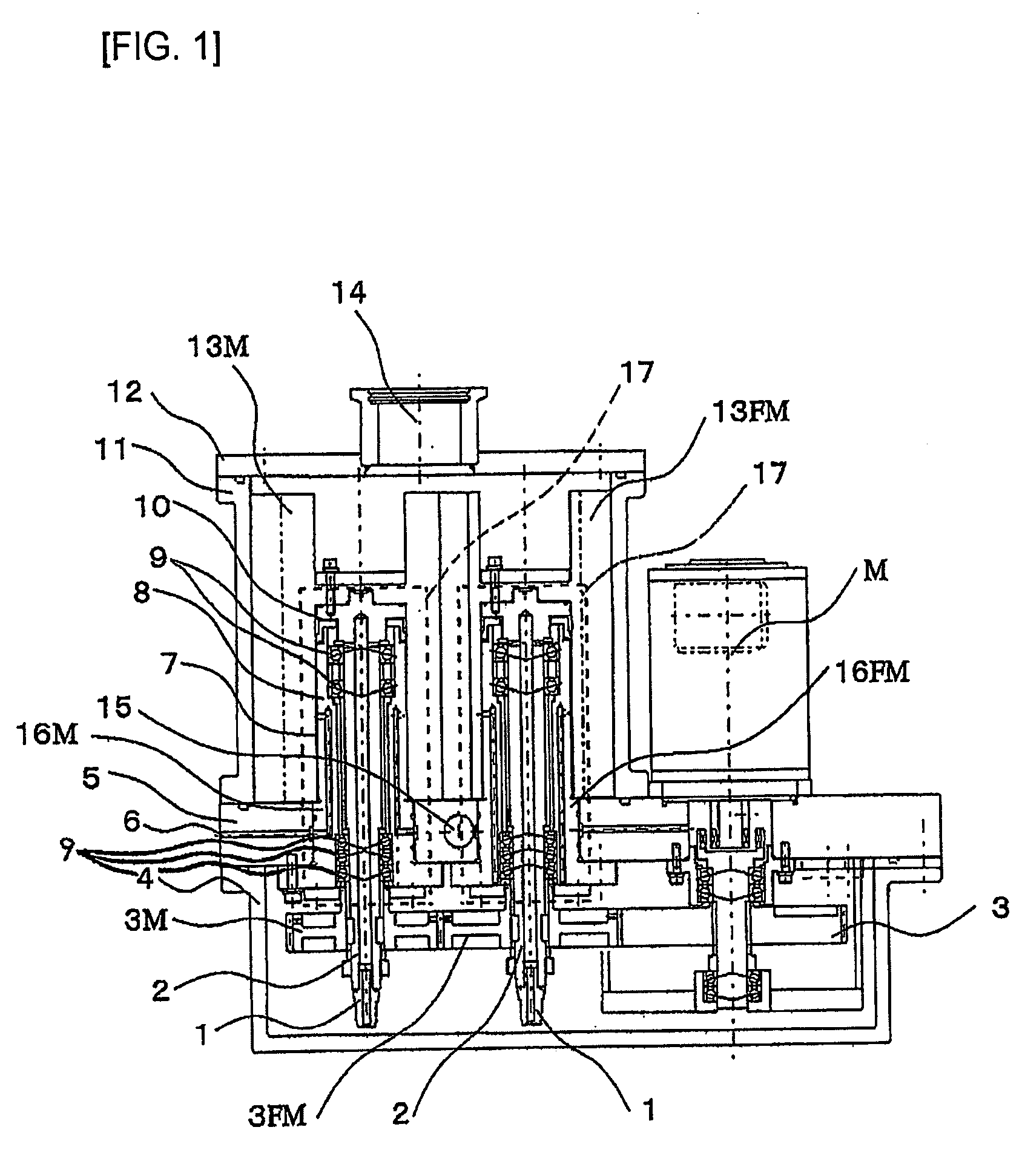
[0057] A screw pump body A comprises a pair of screw rotors 13M and 13FM.

[0058] The screw rotor 13M is a first screw rotor having a plurality of helical land portions and a plurality of helical groove portions. The screw rotor 13FM is a second screw rotor having a plurality of helical land portions and a plurality of helical groove portions. These screw rotors 13M and 13FM rotate about two axes substantially parallel to each other while meshing with each other.

[0059] The screw rotors 13M and 13FM are received in a casing 11 and rotatably supported by a plurality of bearings 9 provided in substantially hollow-cylindrical bearing members 16 (bearing members 16M and 16FM) through shafts 2 supporting the screw rotors 13M and 13FM, respectively. Timing gears 3M and 3FM are attached to the shafts 2 at one-end portions thereof, respectively, so that the pair of screw rotors 13M and 13FM are synchronously rotated through the timing gears 3M and 3FM.

[0060] An inlet port 14 is formed in a ...


PUM


Abstract

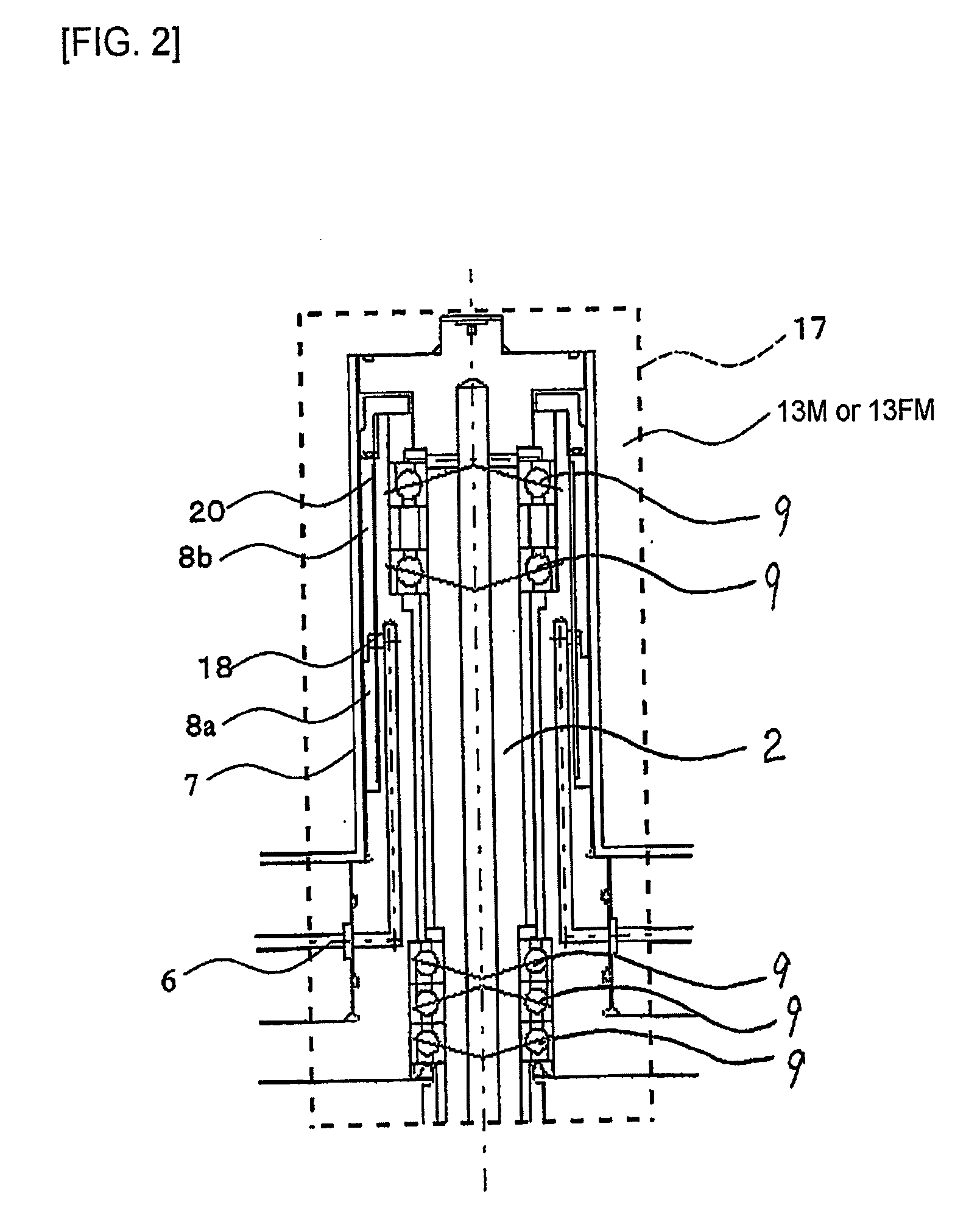
An object of this invention is to provide a vacuum pump having shaft seals that prevent corrosion due to corrosive gas and further ensure smooth operation. A shaft seal structure (17) is provided around an outer circumferential surface of the bearing member (16M, 16FM) located on the cylinder inside of each of the screw rotors (13M, 13FM). The shaft seal structure (17) forms a static pressure seal. A seal gas is introduced between the outer circumferential surfaces of the bearing members (16M, 16FM) and the inner circumferential surfaces (7) of the rotor cylinders of the screw rotors (13M, 13FM) through the bearing members (16M, 16FM).

Description

TECHNICAL FIELD [0001] This invention relates to a vacuum pump and, in particular, relates to a vacuum pump for use in the field of manufacturing semiconductor devices, flat panel display devices, or the like. BACKGROUND ART [0002] Vacuum pumps are used in the semiconductor manufacturing field, the manufacturing field of flat panel display devices and so on, and many other industrial fields that require depressurization. As the vacuum pump, use is made of, for example, a screw pump. The screw pump is disclosed, for example, in Non-Patent Document 1 as a screw type pump. [0003] Generally, the screw pump comprises a pair of screw rotors having a first screw rotor with a plurality of helical land portions and a plurality of helical groove portions (a male rotor with convex thread ridges) and a second screw rotor with a plurality of helical land portions and a plurality of helical groove portions (a female rotor with concave thread grooves) and adapted to rotate about two axes substanti...

Claims


Application Information

Patent Timeline
IPC IPC(8): F01C1/16F01C1/24F03C2/00F04B39/00F04C18/16F04C25/02F04C27/00F04C29/00F04D19/04F04D29/10
CPCF04C18/16F04C27/009F04C2220/30Y10S277/936F04D29/102Y10S277/935F04D19/04
Inventor OHMI
Owner FOUND FOR ADVANCEMENT OF INT SCI
Learn More