Apparatus and Method for Sculpting the Surface of a Joint

a technology of joint surface and sculpting, which is applied in the field of implants for use in minimally invasive total knee replacement surgery, can solve the problems of accelerating wear and degradation of polyethylene bearing surfaces, surgically challenging procedures, and difficulty in all total knee replacement surgeries, and achieves minimal regional variations in the contour of planar resection and promotes load sharing.

Inactive Publication Date: 2007-07-26
CAYENNE MEDICAL INC
View PDF31 Cites 90 Cited by
  • Summary
  • Abstract
  • Description
  • Claims
  • Application Information

AI Technical Summary

Benefits of technology

[0042] When assembling a plurality of sub-components, either to form a femoral component or a tibial component, within the confines of the joint cavity it is beneficial to structure the engaging or joining mechanisms to allow angulation and translation between the sub-components during assembly, then when fully assembled structure the engaging or joining mechanisms according to the constraints required for the femoral or tibial component. Such angulation and translation between adjacent sub-components during assembly being unconstrained or partially constrained as appropriate to make assembly of the sub-components as easy as possible for the surgeon. Such constraints for the fully assembled component to include unconstrained, partially constrained and fully constrained engaging or joining mechanisms between two or more sub-components, and combinations of unconstrained, partially constrained or fully constrained engaging or joining mechanisms connecting the plurality of sub-components that form an implant component.
[0043] The current invention is structured to allow variation in the procedure for implanting a plurality of sub-components forming either a femoral or tibial component. In general, the femoral component is implanted before the tibial component because the space within the joint cavity is more limited after placement of one of the components. The general shape of the femoral sub-components is bulkier than that of the tibial baseplate sub-components, hence the benefit of implanting them first. Alternatively, the tibial sub-components may be implanted first. In an alternative embodiment of the present invention that includes a tibial stem sub-component or a femoral stem sub-component, or both, it may be beneficial to place the stem sub-component(s) first, either into the femoral canal, into the tibial canal or into both. Followed by placement of the femoral condylar sub-components and trochlear sub-component, and then placement of the tibial baseplate sub-components and bearing insert(s). Alternatively, the femoral condylar sub-components and trochlear sub-component may be implanted first, followed by placement of the tibial baseplate sub-components, and then placement of a femoral stem sub-component or a tibial stem sub-component or both followed by placement of the bearing insert(s). In general, the patellar component is implanted last. Alternatively, one or more of the femoral sub-components or the tibial sub-components may be secured to supporting bone before assembly to respective adjacent sub-components. It may also be advantageous to partially assemble femoral sub-components or tibial sub-components outside of the joint cavity, for example passing the femoral medial condylar sub-component into the joint cavity then assembling the lateral condylar sub-component to the trochlear sub-component and passing the assembly into the joint cavity for assembly to the medial condylar sub-component.
[0044] In the case of tri-compartmental knee arthroplasty the articular surfaces of the tibia and patella are generally removed with planar resections which in general have minimal regional variations in the contour of the planar resections; however in preserving the anterior cruciate ligament it may be advantageous to resect the medial and lateral tibial articular surfaces independently which may result in variations between the planar resection of the medial tibial articular surface and that of the lateral tibial articular surface. The articular surfaces of the distal femur, those being the medial and lateral condyles and the trochlea, may be independently sculpted. The regional contour of the supporting bone, that is the contour of the resected bone within each compartment, that is the medial tibiofemoral compartment, the lateral tibiofemoral compartment and the patellofemoral compartment, closely matches that of the respective sub-component; however due to the independent sculpting of the femur within each compartment there may be variations between the prepared bone surfaces in each compartment. Additionally, partial constraint of the assembled interface between sub-components promotes load sharing across all resected surfaces of the supporting bone.

Problems solved by technology

Orientating the separate components one to another, for example aligning the medial and lateral femoral components to one another, or the medial and lateral tibial components to one another, was not addressed in these designs and often left for the surgeon to make free hand resections resulting in a surgically challenging procedure.
Such designs tend to have higher contact pressure which may accelerate wear and degradation of the polyethylene bearing surface.
While implant systems have been developed with fixed bearing elements or mobile bearing elements on the medial and lateral sides of the tibiofemoral joint, systems have not been developed having a combination of a fixed bearing on one side and a mobile bearing on the other side of the tibiofemoral joint.
Two primary difficulties exist with current joint replacement surgeries.
Such difficulties are present in all total joint replacements, including but not limited to ankle, knee, hip, shoulder, wrist and finger.
A difficulty with implanting both modular and non-modular knee implants having either separate femoral and / or tibial components has been achieving a correct relationship between the components.
Surgical instruments available to date have not provided trouble free use in implanting multi-part implants wherein the distal femur, proximal tibia and posterior patella are prepared for precise component-to-component orientation.
While alignment guides aid in accurate orientation of opposing components relative to the axis of the long bones to achieve a restoration of a correct tibiofemoral varus / valgus alignment (usually 4-7 degrees valgus), they provide limited positioning or guidance relevant to correct subcomponent-to-subcomponent alignment in placing a plurality of components to form the articular surface of a femoral component or a tibial component.
Such instrumentation references the bone on which it is placed and does not account for nor attempt to address ligament tension to restore soft tissue balance in a properly aligned total knee.
While surgical instruments available to date aid in accurate varus / valgus alignment, they provide limited positioning or guidance relevant to correct flexion / extension orientation of the femoral, posterior slope of tibial components, nor of external rotation of the femoral component.
If the implants are malaligned, the resulting mechanical axis may be shifted medially or laterally, resulting in an imbalance in the loads carried by the medial or lateral condyles.
This imbalance, if severe, may lead to early failure of the arthroplasty.
Moreover, orientation of the femoral component to the corresponding tibial component, whether with free standing uni-compartmental, bi-compartmental and / or tri-compartmental implants has largely not been addressed.
This may account for the high failure rates in the surgical application of free standing compartmental replacements, used individually or in combination, and as well as for the higher failure rate of uni-compartmental implants relative to total knee implants as demonstrated in some clinical studies.
While efforts are made to tailor the prosthesis to the needs of each patient by suitable prosthesis choice and size, this in fact is problematical inasmuch as the joint physiology of patients can vary substantially from one patient to another.
Altered kinematics can reduce a patient's confidence in the knee's ability to perform demanding tasks, and at times tasks of daily living, to the point of significantly limiting lifestyle and activity level.

Method used


Image

  • Apparatus and Method for Sculpting the Surface of a Joint
  • Apparatus and Method for Sculpting the Surface of a Joint
  • Apparatus and Method for Sculpting the Surface of a Joint

Examples


Embodiment Construction

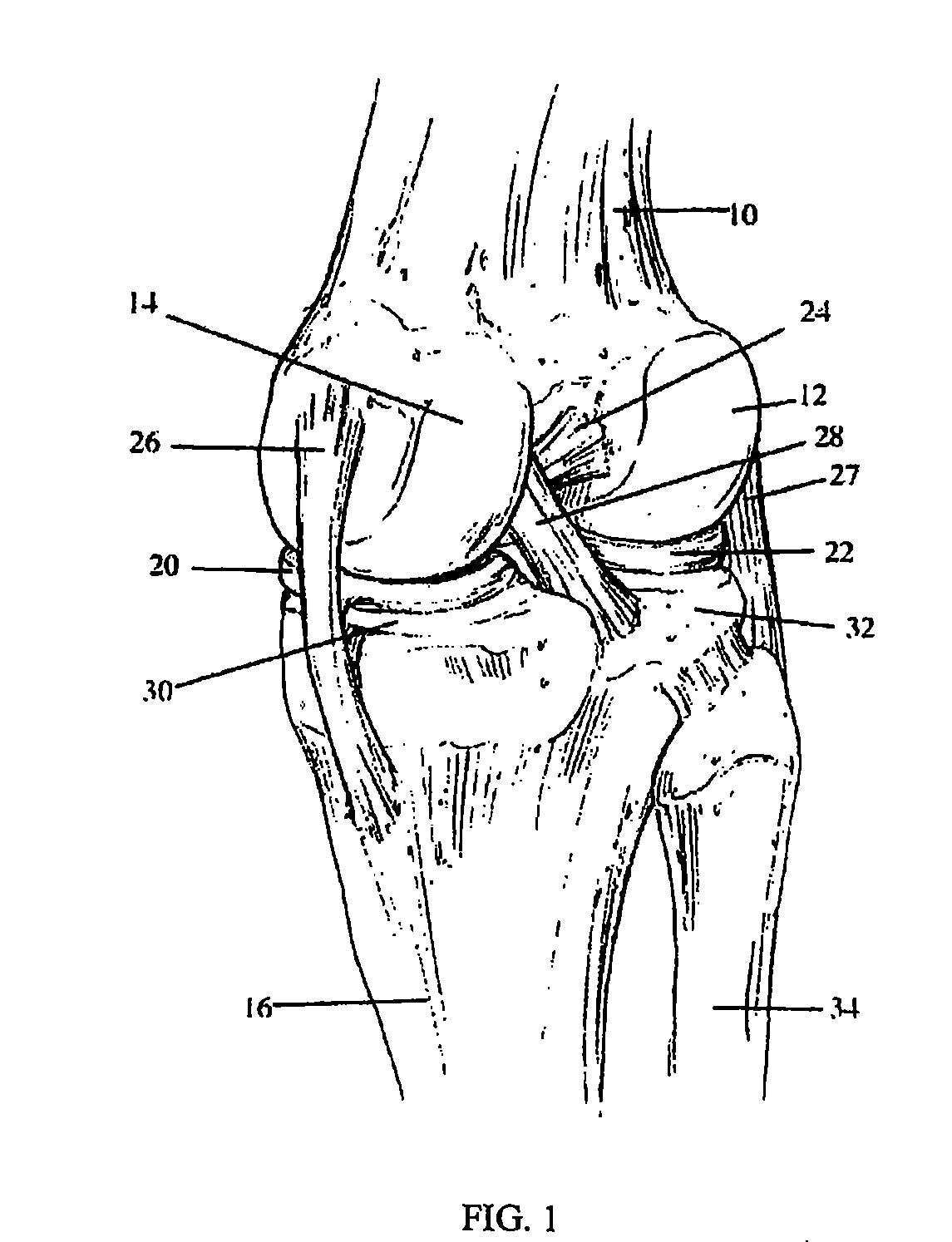
[0108] Knee Joint Anatomy and Surgical Approaches. FIG. 1 illustrates the general anatomy of the knee joint. The femur 10 has the lateral femoral condyle 12 and the medial femoral condyle 14 on its knee-joint articulating surface. The tibia 16 has the lateral meniscus 22 (generally opposite the lateral femoral condyle 12) and the medial meniscus 20 (generally opposite the medial femoral condyle 14) on its knee-joint articulating surface. The ligaments include the anterior cruciate ligament 24, the posterior cruciate ligament 28, the medial collateral ligament 26 and the lateral collateral ligament 27. The medial tibial condyle 30 and the lateral tibial condyle 32 support the menisci 20 and 22, which in turn support the femur 10. Additionally, the fibula 34 engages the tibia 16.

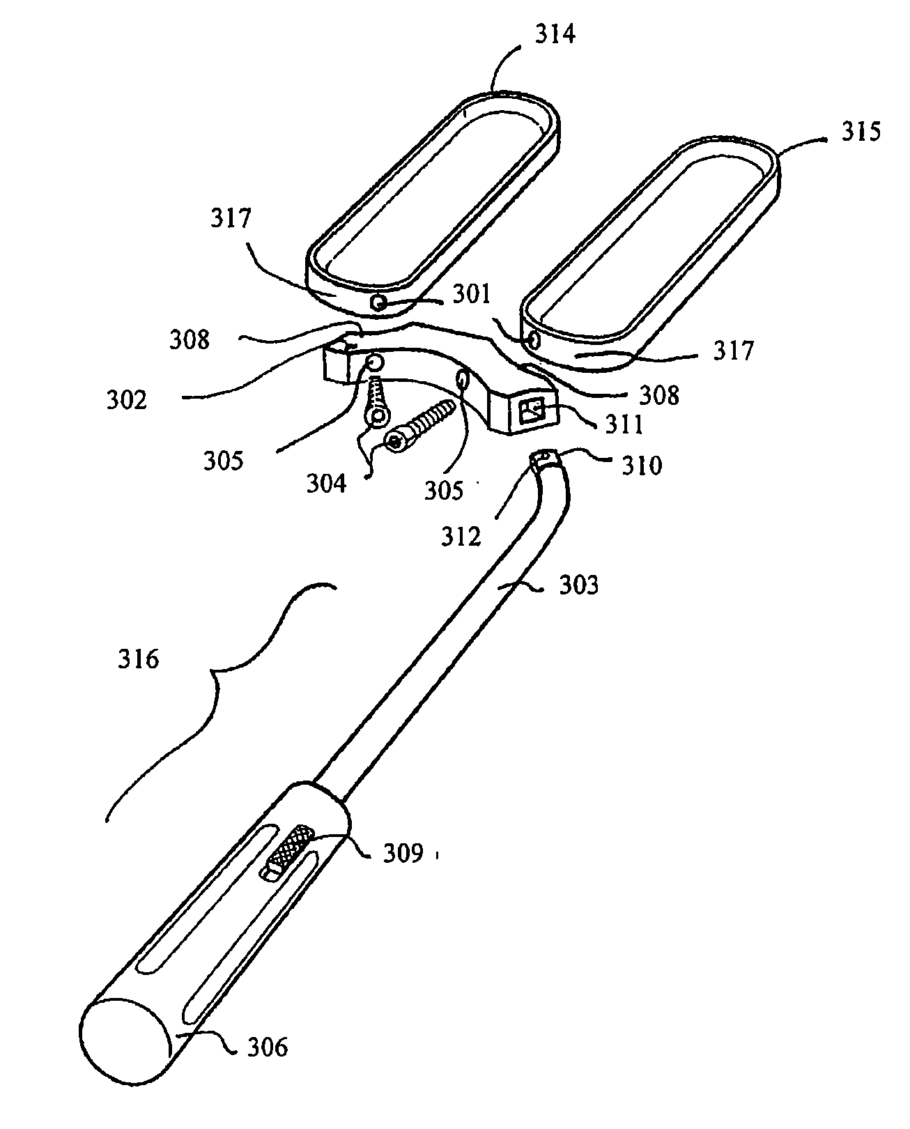
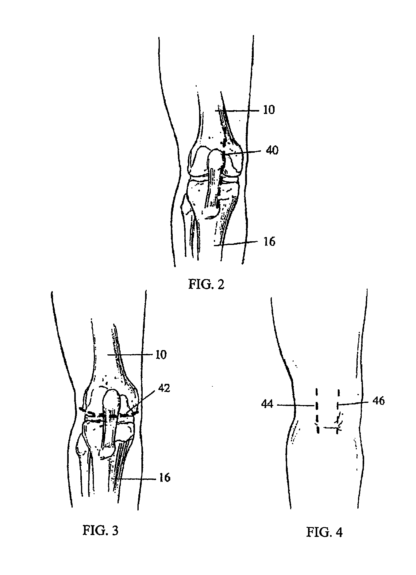
[0109] Typically, a total knee joint replacement involves replacing the articular surfaces of the lateral femoral condyle 12, the medial femoral condyle 14, the medial tibial condyle 30 and the lateral tibial...


PUM


Abstract

The present invention provides a method and device for restoring individual patient joint kinematics using minimally invasive surgical procedures. The instrumentation of the invention sculpts the articular surface of a first bone that normally articulates in a predetermined manner with a second bone. The instrumentation includes a bone sculpting tool and a mount for attaching the tool to the second bone. The implant system is comprised of implants that provide intraoperative surgical options for articular constraint and facilitate proper alignment and orientation of the joint to restore kinematics as defined by the individual patient anatomy.

Description

CROSS REFERENCE TO RELATED APPLICATIONS [0001] This application claims the benefit of U.S. Provisional Patent Application Ser. No. 60 / 701,270, filed Jul. 21, 2005, which is a continuation-in-part of U.S. patent application Ser. No. 11 / 186,485, filed Jul. 20, 2005, which is a continuation-in-part of U.S. provisional patent application Ser. No. 60 / 589,320 filed Jul. 20, 2004, which is a continuation-in-part of U.S. patent application Ser. No. 10 / 159,147 filed May 29, 2002, which is a divisional of U.S. patent application Ser. No. 09 / 882,591 filed Jun. 14, 2001 now U.S. Pat. No. 6,723,102, the entireties of which are hereby incorporated by reference.BACKGROUND OF THE INVENTION [0002] 1. Field of the Invention [0003] This invention relates to implants for use in minimally invasive total knee replacement surgery. More particularly, this invention relates to modular bearing surfaces and mobile-bearing and fixed-bearing modular components in arthroplasty of human joints. [0004] 2. Descript...

Claims


Application Information

Patent Timeline
Patent Type & Authority Applications(United States)
IPC IPC(8): A61F2/00
CPCA61F2/38A61F2/3859A61F2/3877A61F2/389A61F2/4405A61F2002/4687A61F2/461A61F2002/30604A61F2002/30616A61F2002/3895A61F2/442A61F2002/30387A61F2002/30433A61F2002/3863
Inventor ENGH, GERARD A.JOHNSON, WESLEY D.
Owner CAYENNE MEDICAL INC
Why Eureka
Try Eureka