Magnetic field modling device, die and method for magnetic field molding

a technology of magnetic field and modling device, which is applied in the direction of electrical equipment, metal-working equipment, and auxillary shaping equipment, etc., can solve the problems of high production cost, high labor intensity, and increased defectiveness of molded bodies, so as to improve the resistance of coating film, high hardness, and low friction coefficient

Inactive Publication Date: 2007-08-02
TDK CORPARATION
View PDF3 Cites 7 Cited by
  • Summary
  • Abstract
  • Description
  • Claims
  • Application Information

AI Technical Summary

Benefits of technology

[0018]The present invention can improve resistance of coating film, which coats a die at least partly, to wear by a ferrite material (powder) in the slurry by using a material of high hardness and low friction coefficient. As a result, the presen

Problems solved by technology

However, use of a releasing agent may cause chipping or cracking of the molded body to increase percent defective, when its quantity is not adequate.
This increases releasing agent consumption to cause a higher production cost.
Still more, spreading a releasing agent needs time-consuming labor, which also lead to reduced productivity.
Ferrite powder for magnets itself causes problems due to its high hardness.
The particles are movable,

Method used


Image

  • Magnetic field modling device, die and method for magnetic field molding
  • Magnetic field modling device, die and method for magnetic field molding
  • Magnetic field modling device, die and method for magnetic field molding

Examples


examples

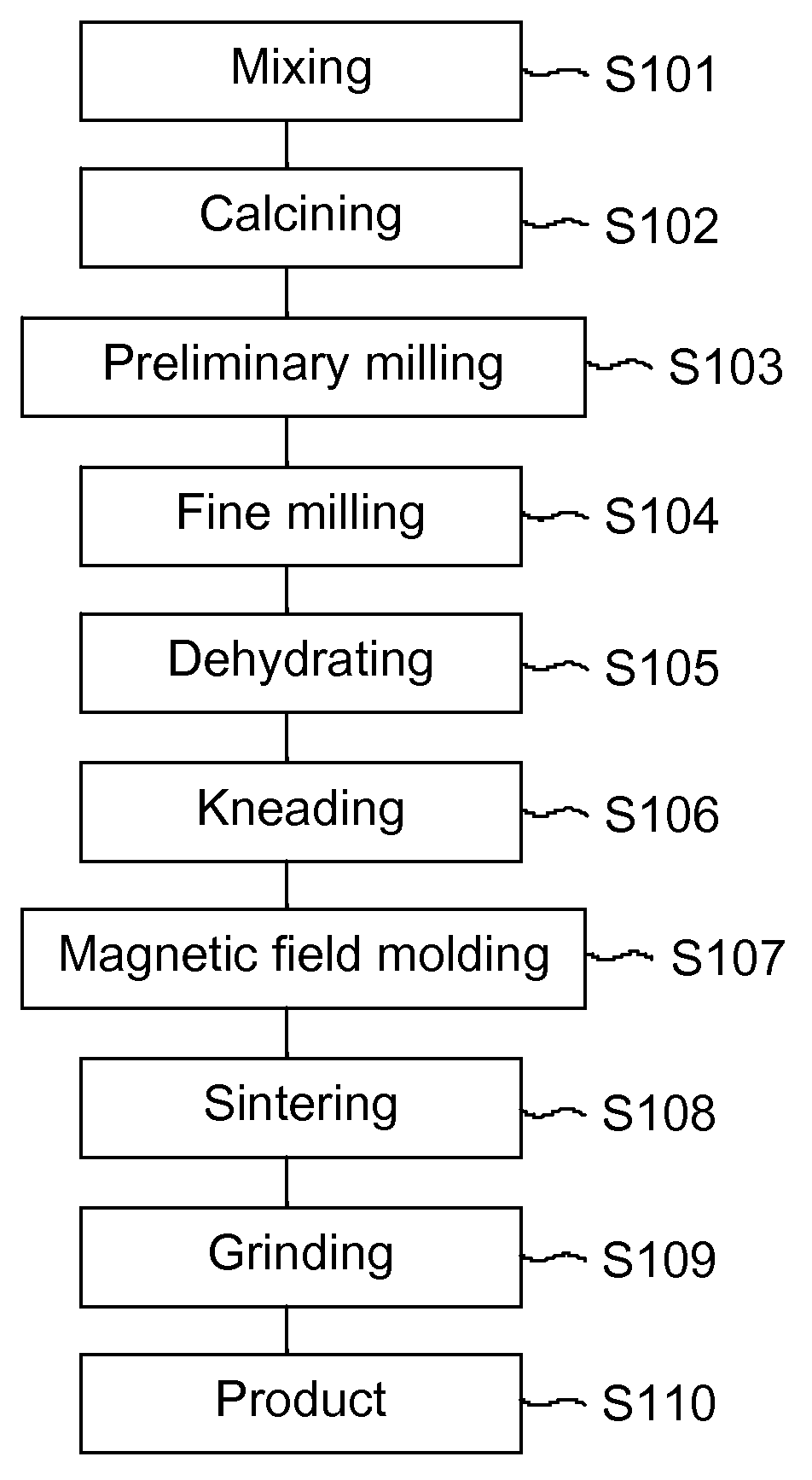
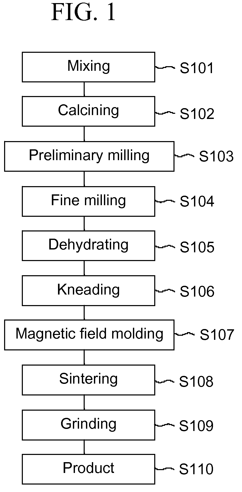
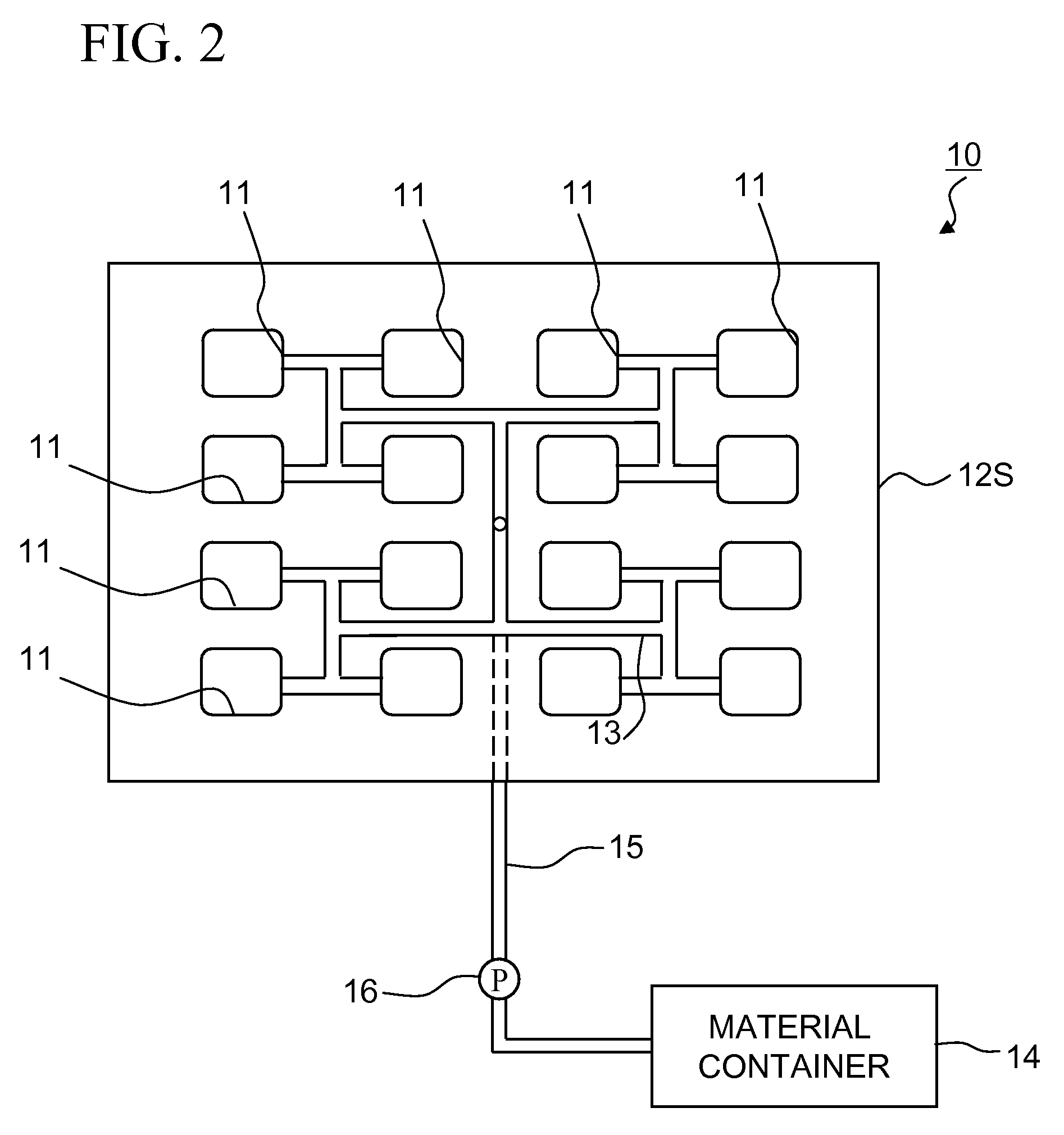
[0048]A slurry was prepared by the process illustrated in FIG. 1. A ferrite material (finely milled powder) used in the slurry was strontium ferrite (Vickers hardness Hv: 800), which was dispersed in water as a dispersion medium. The slurry was injected into the disc-shape cavity 11 (diameter: 30 mm) individually by the pump 16 working at a constant pressure.

[0049]When the cavity 11 was filled with a given quantity of the slurry, the shutoff valve 19 was closed to close the system P. Then, the slurry was compressed while the upper die 12A and lower die 12B were kept closed. Then, the upper die 12A and lower die 12B were opened, and the resulting molded body was withdrawn.

[0050]The upper surface of the lower die 12B had been coated with the coating film 30 of diamond-like carbon. A total of four types of the film were formed, each having a Vickers hardness Hv of 800, 850, 1,600 or 3,200 (Comparative Example 2 and Examples 1 to 3). The coating film 30 was 1 μm thick and had a friction...


PUM

PropertyMeasurementUnit
Digital informationaaaaaaaaaa
Luminous fluxaaaaaaaaaa

Abstract

The objects of the present invention are to provide a durable magnetic field molding device for producing molded bodies for ferrite magnets, which needs a controlled amount of releasing agent, reduces production cost and improves productivity, and die and magnetic field molding method. The lower die 12B of the die 12 is coated, on the surface which defines the cavity 11, with the coating film 30 with a high hardness and a low friction coefficient, which improves resistance of the lower die 12B surface to wear by the solid component (fine powder) in the slurry, thereby greatly improving durability of the coating film 30 itself and reducing lubricant usage.

Description

BACKGROUND OF THE INVENTION[0001]1. Field of the Invention[0002]The present invention relates to a magnetic field molding device suitable for wet molding, die and method for magnetic field molding.[0003]2. Description of the Related Art[0004]Ferrite (sintered) magnets, now predominating magnets, are produced from starting material mixture with a given composition, which are calcined into a ferrite, milled to a sub-micron size to produce powder of ferrite particles. The powder is then compression-molded in a die placed in a magnetic field (hereinafter referred to as magnetic field molding) to form a molded body and sintered to produce a ferrite magnet (as disclosed Patent Document 1, for example).[0005]Magnetic field molding processes broadly fall into two categories, dry process and wet process, where the ferrite powder is dried and molded in the former and the slurried powder is molded in the latter.[0006][Patent Document 1] Japanese Patent Laid-Open No. 2005-317911SUMMARY OF THE I...

Claims


Application Information

Patent Timeline
IPC IPC(8): H05B6/00
CPCB22F2003/247B22F2998/10H05B6/80H01F41/0273H01F41/0266C04B2235/605C04B2235/602C04B2235/3213B29C33/10B29C43/003B29C43/56B29C2043/568B29K2303/06B30B15/302C04B35/2683B22F1/0003B22F1/0085B22F9/04B22F3/02B22F3/10B22F3/24B22F1/00B22F1/142
Inventor SAITO, NORIHISAMASUDA, TOMOHIRO
Owner TDK CORPARATION
Why Eureka
Try Eureka