Two-color flame imaging pyrometer

US20070177650A1Inactive Publication Date: 2007-08-02DIAMOND POWER INT

Image

  • Two-color flame imaging pyrometer
  • Two-color flame imaging pyrometer
  • Two-color flame imaging pyrometer

Examples


Embodiment Construction

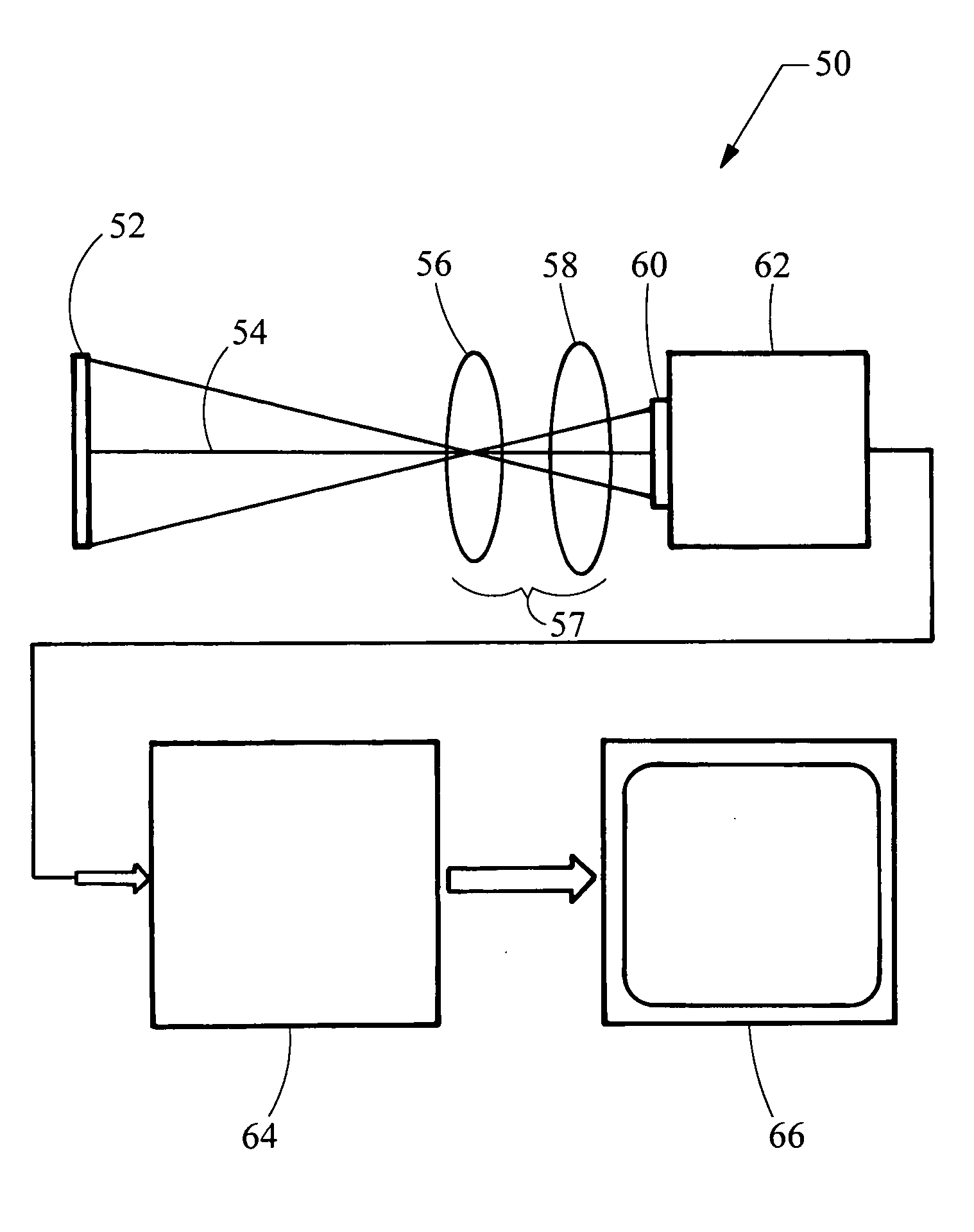
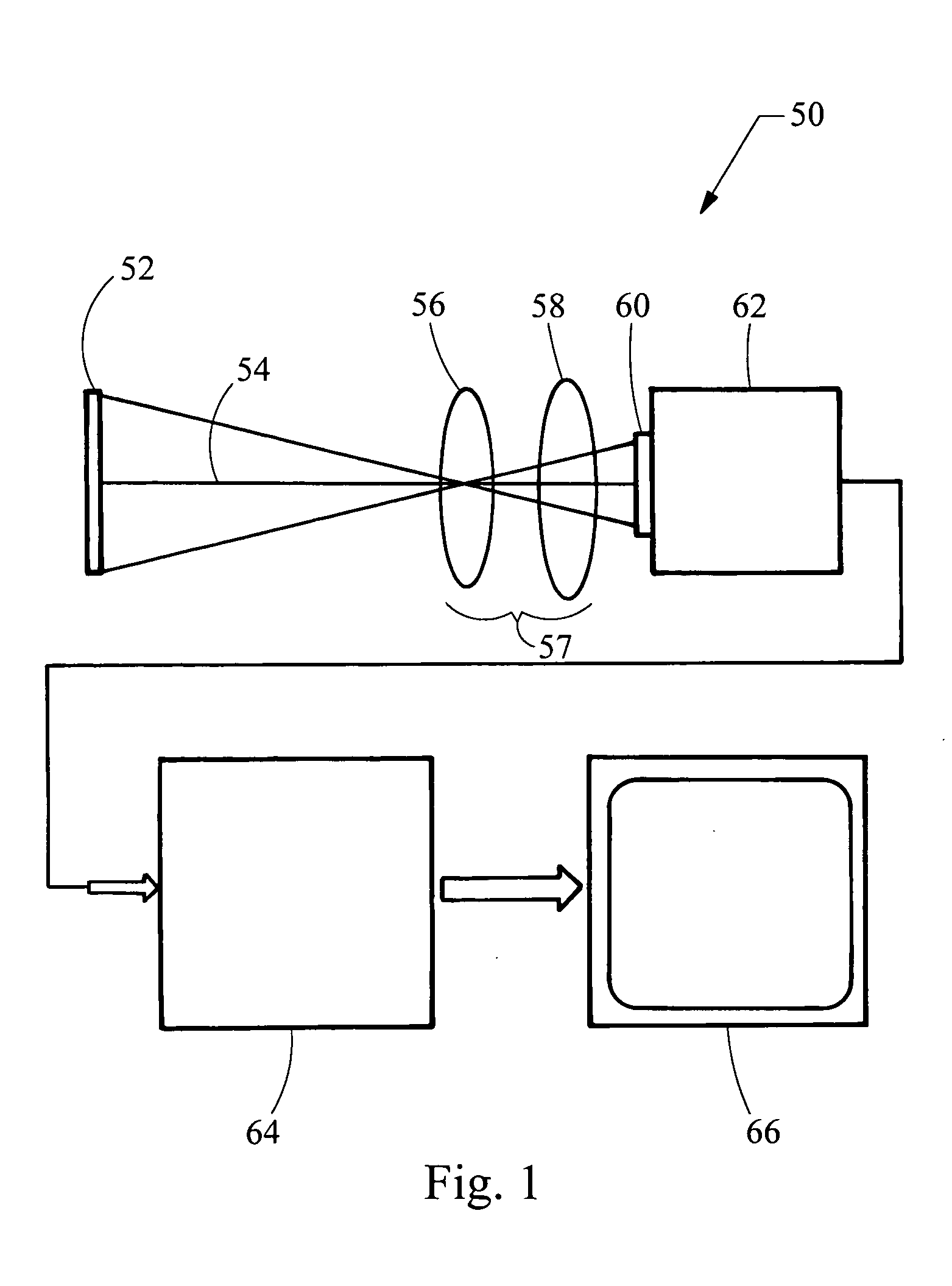
[0014] Referring now to FIG. 1, a system embodying the principles of the present invention is illustrated therein and designated at 50. As its primary components, the system 50 includes an optical system 57 and a color video camera 62.

[0015] The system 50 provides for remote viewing and an isothermal contour temperature mapping of an object 52, such as a furnace, boiler combustion zones, and burner flames. Although primarily intended for fireside furnace or boiler temperature measurements, the system 50 can also accurately measure temperatures of any object or medium that are radiating within the spectral and illuminance ranges of the color camera 62. The object 52 emits optical radiation as denoted by line 54. The optical radiation 54 is transmitted from the object 52 and is received by the optical system 57.

[0016] The optical system 57 includes an objective lens 56 that forms a focused image of the object 52 on the color detector 60 of the color camera 62. The objective lens 56 ...


PUM


Abstract

The system uses a color camera and an optical system to map two colors emitted from an object such as a furnace, boiler combustion zone, or burner flame into a temperature image. The color camera utilizes a color video chip with interspersed pixels for each color to reduce alignment issues and utilize the same optical path. In addition, the optical system utilizes a dual band pass optical filter thereby eliminating the number of optical elements and minimizing radiation loss through the optical system thereby improving the dynamic range of the system.

Description

BACKGROUND OF THE INVENTION [0001] 1. Field of the Invention [0002] The present invention generally relates to a system for optical pyrometry for use in combustion devices. [0003] 2. Description of Related Art [0004] Optical pyrometry is a measurement technique in which the temperature of an object or medium is determined based on the spectral radiant emittance of the object or medium. Such techniques are used in various applications, including evaluation of combustion processes and the state of fouling of surfaces within a large scale combustion device. Typically, video pyrometers for such applications utilize two optical paths such that one wavelength band of light is processed down the first optical path and a second wavelength band of light is processed down the second optical path. Each optical path creates two separate images that are focused onto two monochrome video cameras or on two non-overlapping areas of a single monochrome video camera. One such design is provided in U....

Claims


Application Information

Patent Timeline
02 Aug 2007
Publication
US20070177650A1
IPC
G01J5/00
CPC
G01J5/0014; G01J5/0044; G01J5/025; G01J5/602; G01J5/0846; G01J5/0862; G01J5/08; G01J5/0802
Inventors
HUSTON, JOHN T.; YOUSSEF, SIMON F.