Laser atom probe methods

a technology of atom probes and lasers, applied in the field of atom probes, can solve the problems of data depletion, difficult to align the beam onto the area of interest on the specimen, difficult to compound, etc., and achieve the effects of enhancing the versatility of an atom probe, enhancing the use value of the atom probe, and enhancing the susceptibility to ionization

Active Publication Date: 2007-08-09
CAMECA INSTR
View PDF14 Cites 22 Cited by
  • Summary
  • Abstract
  • Description
  • Claims
  • Application Information

AI Technical Summary

Benefits of technology

[0019] The utility of the atom probe is further enhanced if the laser (or other energy beam) contains laser light (or other energy) of at least two different wavelengths when it reaches the specimen. Since different materials can exhibit greater susceptibility to ionization at energies at different wavelengths, using a mixture of wavelengths can enhance the versatility of an atom probe by allowing it to more efficiently analyze a wide range of materials. While a mixture of wavelengths can be generated by using multiple lasers and combining their beams with the use of dichroic mirrors or other elements, a particularly preferred arrangement is to use a single laser (with emitted laser light at a single wavelength), and generate harmonic wavelengths in the same beam by use of nonlinear crystals or other harmonic-generating optics. Using a single laser avoids the need to synchronize pulse timing among different lasers, and also avoids the cost and space issues arising from use of multiple lasers.
[0020] Cost and space issues are also reduced if the laser is placed outside of the vacuum chamber containing the specimen mount and detector, and if the laser delivers its beam to the specimen through a window defined in the vacuum chamber (with intermediate mirrors, lenses, or other optical elements being used along the beam if needed). This avoids the need for a laser configured for high-vacuum environments (which can enhance expense), and also avoids the need for the laser to occupy the limited available space within the vacuum chamber. Locating the laser outside the chamber (or at any other location which is distant from the specimen mount) can lead to greater problems with beam alignment on the specimen, but by use of the aforementioned alignment method, these difficulties can be at least partially overcome.
[0021] Some of the aforementioned difficulties may also be at least partially alleviated if the aperture of the counter electrode is configured to receive a laser or other energy beam at the entry of the aperture, and concentrate the energy beam before it leaves the exit of the aperture so that the beam is focused on the specimen with greater intensity. This may be done, for example, by configuring the electrode aperture as a concentrating reflector having a parabolic, hyperboloid, or other configuration which internally reflects the beam energy as it travels from a larger aperture entry to a smaller aperture exit so that the incident beam is concentrated to greater intensity when emitted onto the specimen. Such an arrangement can at least partially compensate for beam misalignment by “catching” and redirecting a misaligned beam so that it is focused on the specimen. Since such an arrangement can better tolerate minor beam misalignment, it is also well suited to receive multiple laser or other energy beams and direct any misaligned beams onto the specimen.

Problems solved by technology

However, situating the laser such that its beam is aligned through the aperture, and using a smaller beam size than in prior atom probes, generates significant difficulties: aligning the beam through the aperture will almost inevitably situate the laser more distantly from the specimen than if the conventional arrangement is used (wherein the laser and specimen are situated on the same side of the counter electrode and its aperture plane, with the laser situated adjacent to the specimen), which makes it difficult to align the beam onto the area of interest on the specimen.
This difficultly is compounded as the spot size is decreased, particularly since a smaller beam will be more subject to “drift” (i.e., gradual misalignment over time owing to vibration, laser imperfections, thermal expansion / contraction of the components between the laser and the specimen mount, etc.).
Thus, even if a beam can be focused on a specimen apex or other area of interest at the outset of a data acquisition session, data may degrade over time as the beam drifts with usage of the laser.

Method used


Image

  • Laser atom probe methods
  • Laser atom probe methods
  • Laser atom probe methods

Examples


Embodiment Construction

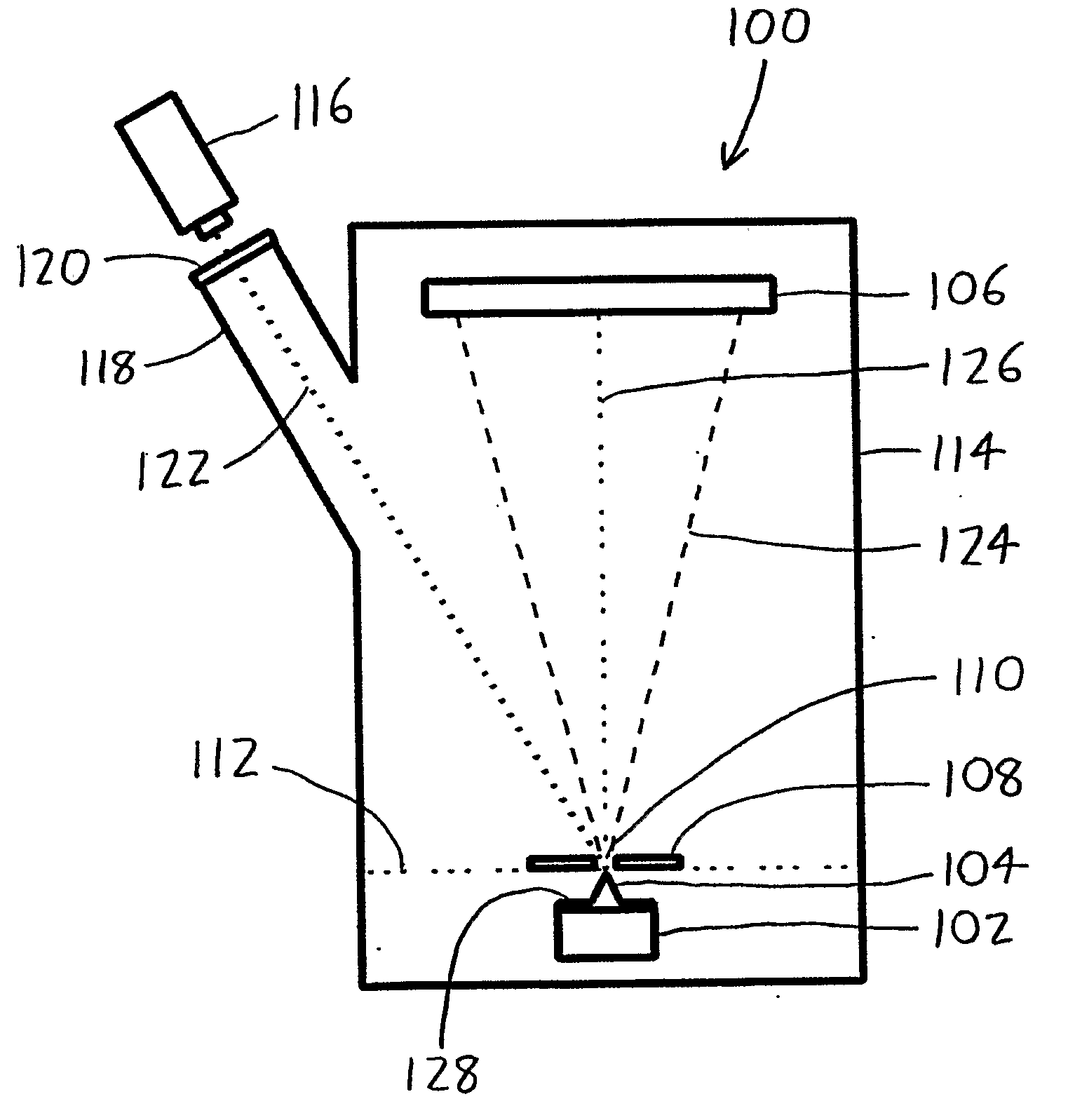
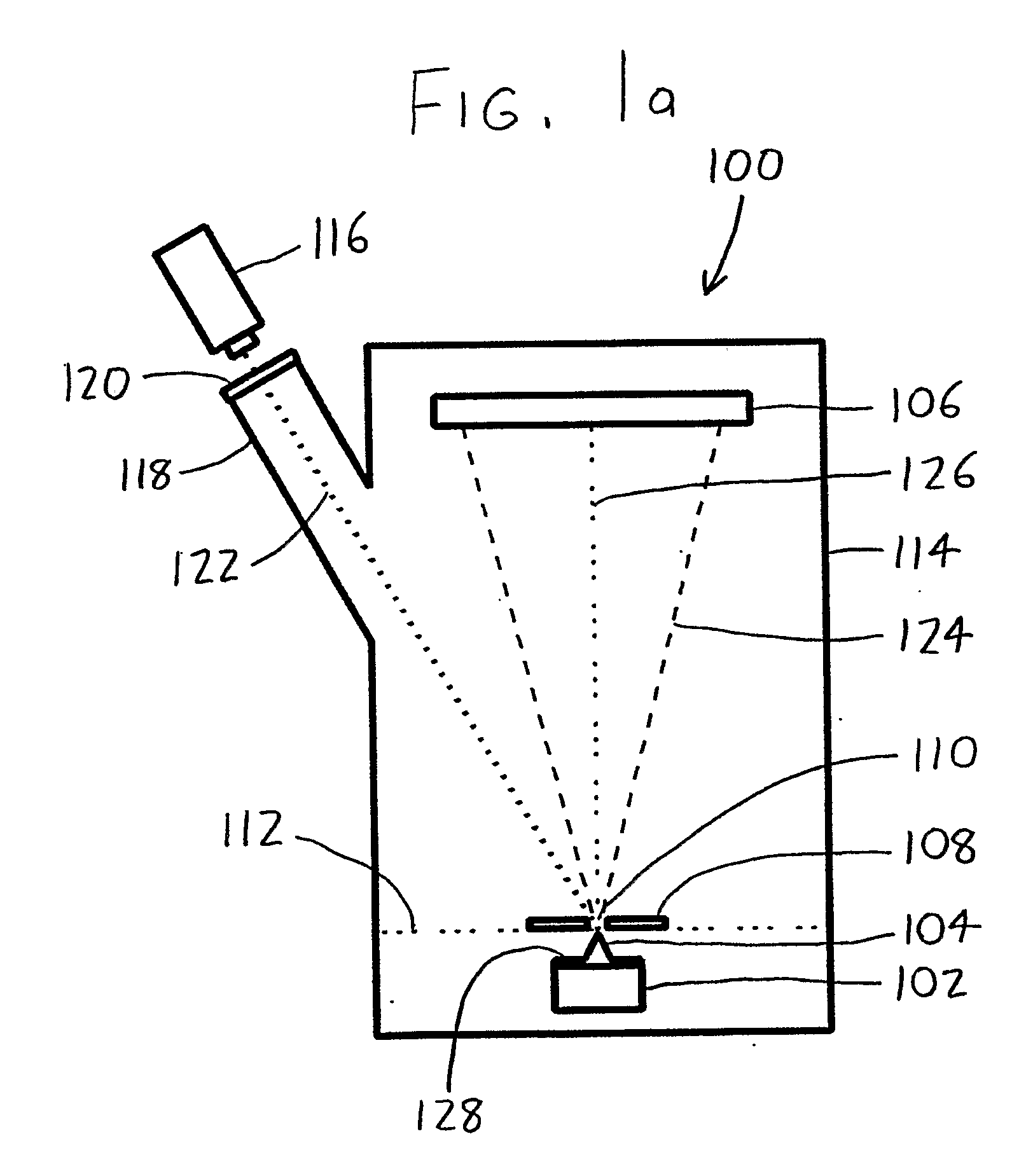
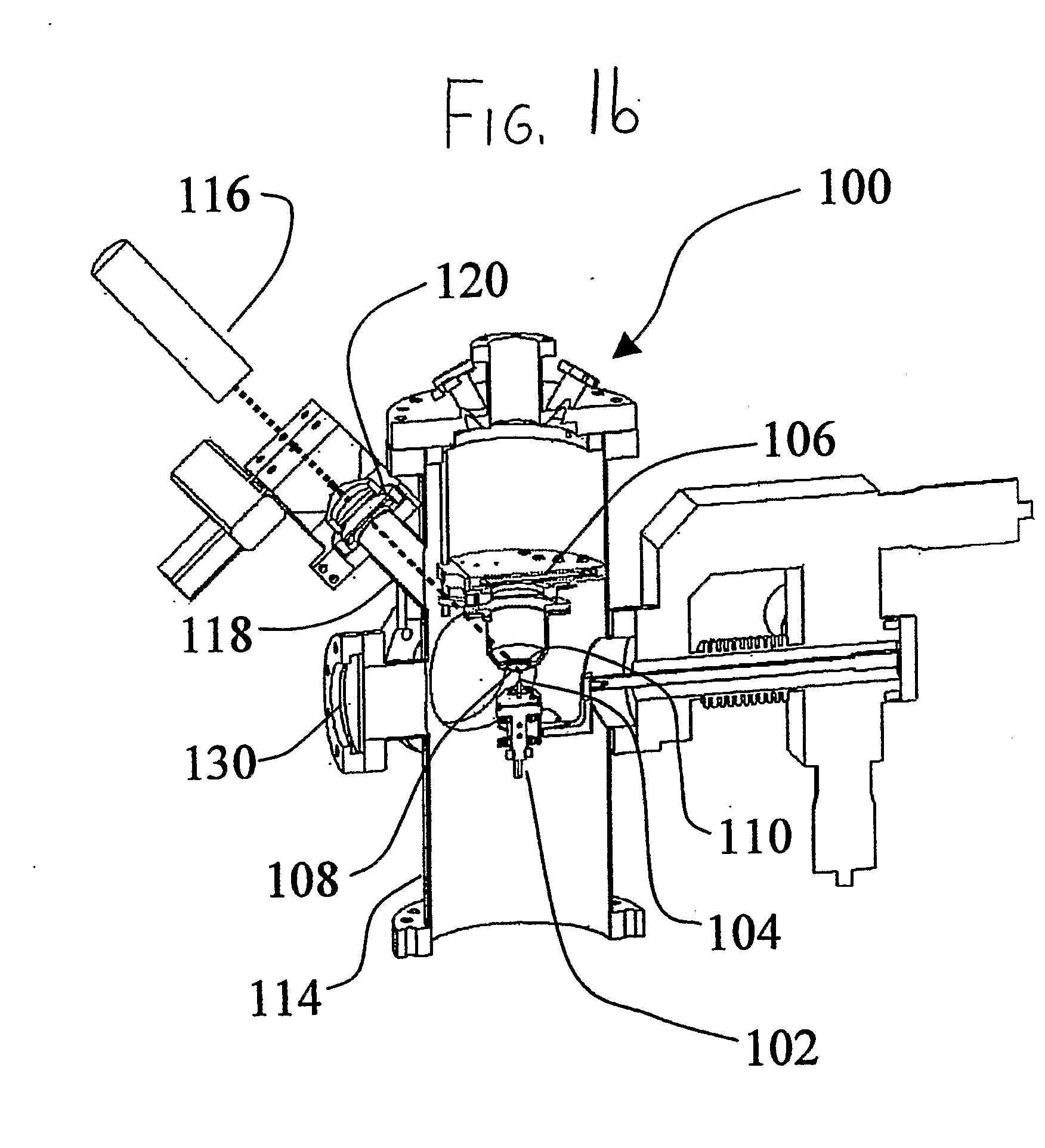
[0030] Turning initially to FIGS. 1a and 1b, an exemplary laser atom probe, depicted generally by the reference numeral 100, is illustrated in both schematic form (FIG. 1a) and in a perspective view of an actual prototype (FIG. 1b). The laser atom probe 100 includes a specimen mount 102 with a specimen 104 mounted thereon, an opposing detector 106 for receiving ions evaporated from the specimen 104, and a counter electrode 108 situated between the specimen mount 102 and the detector 106. The specimen mount 102 is movable to allow positioning of the specimen 104 within or closely spaced from the aperture 110 of the counter electrode 108, with the apex or other area of interest on the specimen 104 preferably being situated at the aperture plane 112 which defines the entry of the aperture 110. A vacuum chamber 114 surrounds all of the foregoing components. As can be seen from the references noted in the Bibliography provided later in this document, the foregoing arrangement of the spec...


PUM

PropertyMeasurementUnit
diameteraaaaaaaaaa
diameteraaaaaaaaaa
sizeaaaaaaaaaa

Abstract

A laser atom probe (100) situates a counter electrode between a specimen mount and a detector (106), and provides a laser (116) having its beam (122) aligned to illuminate the specimen (104) through the aperture (110) of the counter electrode (108). The detector, specimen mount (102), and/or the counter electrode may be charged to some boost voltage and then be pulsed to bring the specimen to ionization. The timing of the laser pulses may be used to determine ion departure and arrival times allowing determination of the mass-to-charge ratios of the ions, thus their identities. Automated alignment methods are described wherein the laser is automatically directed to areas of interest.

Description

CROSS-REFERENCE TO RELATED APPLICATIONS [0001] This application claims priority under 35 USC §119(e) to U.S. Provisional Patent Application 60 / 576,557 (filed 3 Jun. 2004).FIELD OF THE INVENTION [0002] This document concerns an invention relating generally to atom probes, also known as atom probe microscopes. BACKGROUND OF THE INVENTION [0003] The atom probe (also referred to as an atom probe microscope) is a device which allows specimens to be analyzed on an atomic level. A basic version of a conventional atom probe might take the following form. A specimen mount is spaced from a detector, generally a microchannel plate and delay line anode. A specimen is situated in the specimen mount, and the charge (voltage) of the specimen holder is adapted versus the charge of the detector such that atoms on the specimen's surface ionize and “evaporate” from the specimen's surface, and travel to the detector. Generally, the voltage of the specimen is pulsed so that the pulses trigger evaporatio...

Claims


Application Information

Patent Timeline
Patent Type & Authority Applications(United States)
IPC IPC(8): G01N23/00H01J37/285H01J37/304
CPCH01J37/3045G01N23/22H01J49/0004H01J37/285G01Q60/00H01J37/26
Inventor BUNTON, JOSEPH H.OLSON, JESSE D.
Owner CAMECA INSTR
Why Eureka
Try Eureka