Method and apparatus for controlling an electric motor

a technology of electric motor and control method, which is applied in the direction of electronic commutation motor control, speed/accelaration control using electric means, transportation and packaging, etc., can solve the problems of limited controllability, limited usefulness, damage to the electric motor,

a technology of electric motor and control method, which is applied in the direction of electronic commutation motor control, speed/accelaration control using electric means, transportation and packaging, etc., can solve the problems of limited controllability, limited usefulness, damage to the electric motor,

US20070182350A1Inactive Publication Date: 2007-08-09INMOTION TECH CO LTD

Image

  • Method and apparatus for controlling an electric motor
  • Method and apparatus for controlling an electric motor
  • Method and apparatus for controlling an electric motor

Examples


Embodiment Construction

[0082] The preferred embodiments of the invention will be described in terms of an electric traction system for an electric vehicle. However, it is to be appreciated that the present invention is not to be so limited. Indeed, it is envisaged that the method and apparatus of the present invention will also be applicable to other devices that include a permanent magnet electric motor electric motor, such as electric powered machines, electric power tools, electric powered winches and the like.

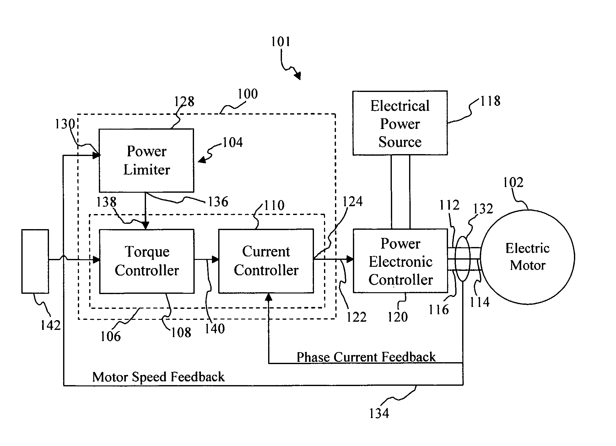
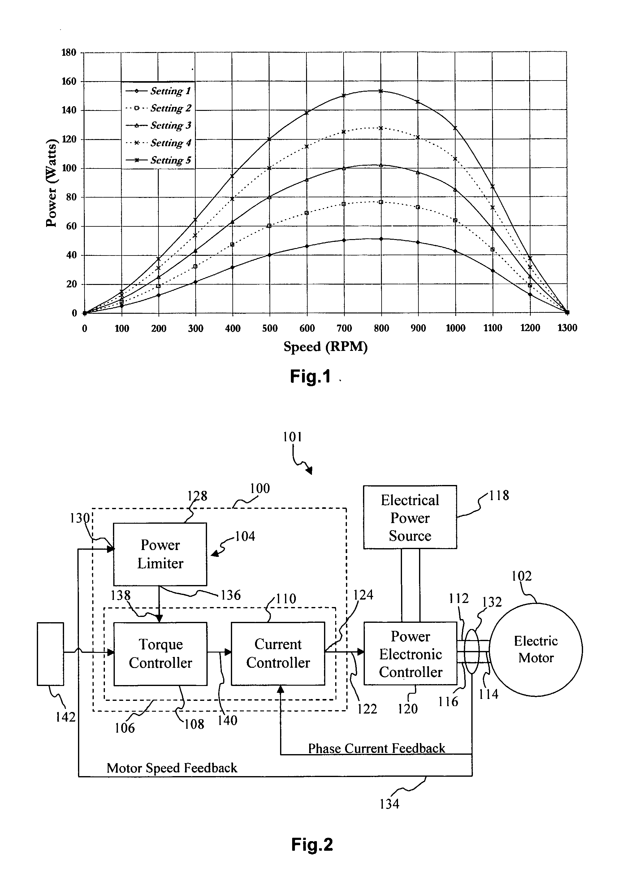
[0083] In FIG. 2, a control system 100 in accordance with an embodiment of the invention for controlling a permanent magnet type electric motor 102 (hereafter referred to as the “electric motor”) of an electric traction system 101 for a vehicle.

[0084] As is shown, the control system 100 includes a limiter means 104 and a control means 106. The control means 106 is shown here as a torque control means 108 and a current control means 110.

[0085] The control system 100 may be synthesised as an ana...


PUM


Abstract

The present invention provides a method for controlling the output power of a permanent magnet electric motor (102) using a control means (106). The control means (106) includes a means (134) for measuring motor speed (134) and motor phase current (134), and a means for controlling motor phase current (110) to a desired level. A known relationship between motor phase current and motor torque is then employed by a torque controller so that motor shaft torque can be controlled. A power limiting means (128) then limits the output mechanical power of the motor by dividing a limit value of power by the motor speed to produce a maximum allowable torque setting for that speed.

Description

FIELD OF THE INVENTION [0001] The present invention relates to a method of and apparatus for controlling a permanent magnet type electric motor. In a typical application, the method and apparatus may be used to control a permanent magnet type electric motor for a battery powered electric vehicle such as a bike, car, boat or the like. BACKGROUND TO THE INVENTION [0002] Electric motors are used in a variety of different applications. One such application includes providing an electric traction system for electric vehicles. [0003] Generally speaking, in electric vehicles which employ electric traction, electrical power is supplied to an electric motor from a suitable electrical power source (such as a battery) through a motor drive circuit. Typically, the electrical power supplied to the electric motor is regulated (for example, by increasing or decreasing an effective voltage which is supplied to the electric motor) by a control system associated with the motor drive circuit so as to ...

Claims


Application Information

Patent Timeline
09 Aug 2007
Publication
US20070182350A1
IPC
H02P7/00; B60L15/20; G05D13/62
CPC
Y02T10/645; Y02T10/644; Y02T10/7275; G05D13/62; H02P7/00; B60L15/20; Y02T10/64; Y02T10/72
Inventors
PATTERSON, DEAN JAMES; CAMILLERI, STEVEN PETER