Method and device for monitoring oil oxidation in real time by measuring fluorescence

a technology of fluorescence and oil oxidation, which is applied in the direction of fluorescence/phosphorescence, brush, analysis by material excitation, etc., can solve the problems of anti-oxidant additive package depletion, base oil oxidation, anti-oxidant additive depletion,

Inactive Publication Date: 2007-08-16
KOREA INST OF SCI & TECH
View PDF10 Cites 71 Cited by
  • Summary
  • Abstract
  • Description
  • Claims
  • Application Information

AI Technical Summary

Benefits of technology

[0015] It is an object of the present invention to overcome the problems of the prior art and provide a low-cost and simply constructed device for monitoring oil oxidation capable of being mounted to mechanical equipments so as to detect the power of fluorescence emission of oil in real time as an indication of oil oxidation.

Problems solved by technology

As the oil degrades, the anti-oxidant additive package becomes depleted and the base oil oxidizes.
Over time, the anti-oxidant additives become depleted until they can no longer effectively protect the base oil.
While the cost of the lubricant itself may be insignificant, the numerous factors for potential collateral damage to the machine are corrosion, varnishing, loss of lubricity, poor demulsibility, filter plugging, etc.
However, the above techniques are unacceptable for an on-line oil monitoring system due to their complexity and high cost of equipment.
However, the above method based on the measurement of the dielectric constant is disadvantageous in that it is incapable of recognizing the main reason for the oil degradation—fuel content, water content, oil oxidation or particle contamination.
However, the above detecting method has the disadvantages of low reliability and complication of replacing the used polymer beads every time when the degraded oil is changed by new one.
The main problem in applying the fluorescence analysis technique to the oil quality estimation is that there is an influence of high optical oil density on recording the signal of the fluorescence emission.
However, the device is rather complex for on-board realization and further needs expensive equipment.
However, this technique must use two path-lengths for fluorescence emission measurement and optical density measurement, thereby complicating the detection process and the associated device.
As discussed above, the above prior art devices and methods for monitoring oil oxidation have certain drawbacks and limitations in application.

Method used


Image

  • Method and device for monitoring oil oxidation in real time by measuring fluorescence
  • Method and device for monitoring oil oxidation in real time by measuring fluorescence
  • Method and device for monitoring oil oxidation in real time by measuring fluorescence

Examples


Embodiment Construction

[0037] Preferred embodiments of the present invention will now be described with reference to the accompanying drawings.

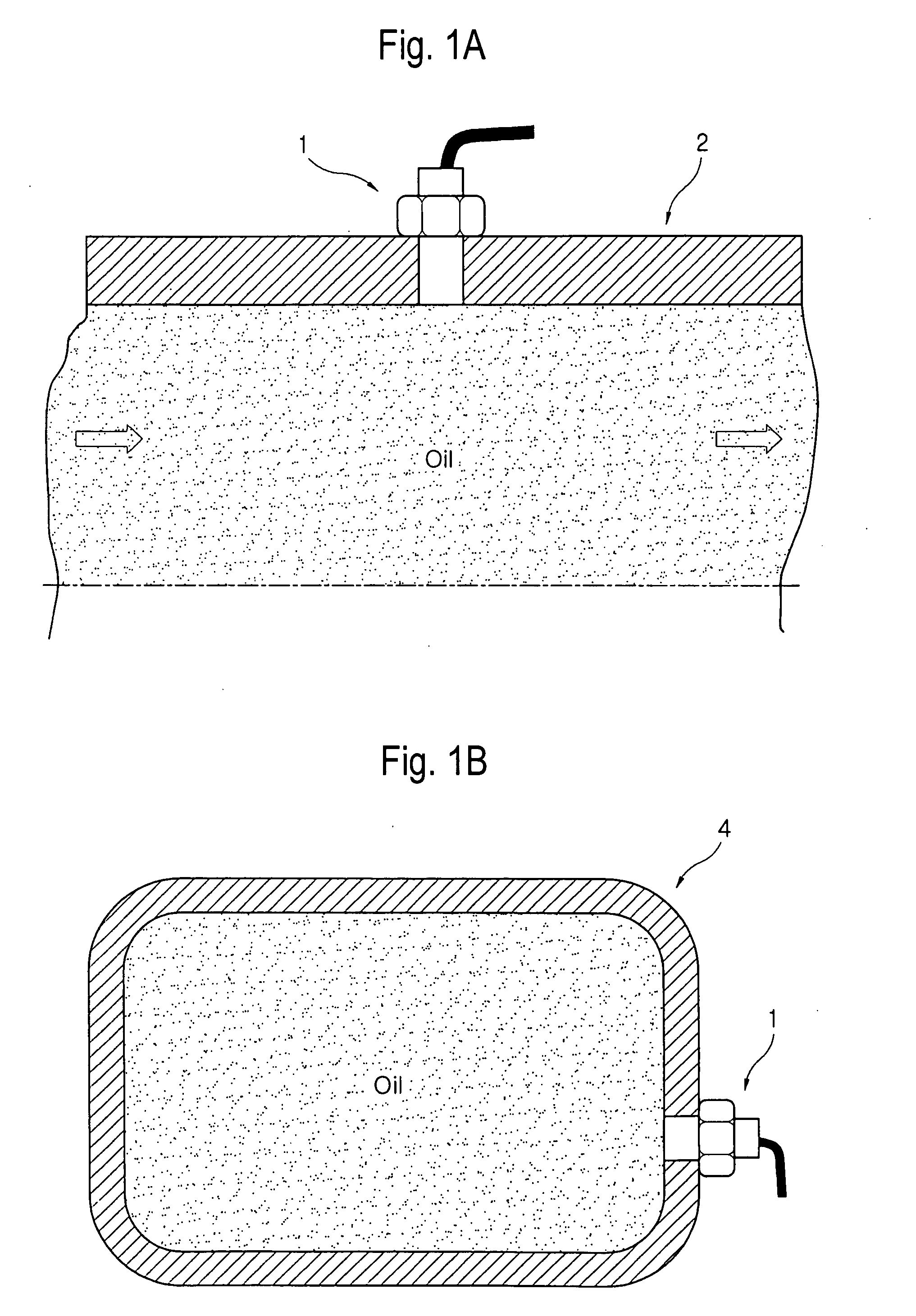
[0038] As shown in FIGS. 1A and 1B, an oil oxidation monitoring device 1, which is constructed in accordance with the present invention, can be installed to a wall of an oil circulation line 2 and an oil tank 4 of mechanical equipment.

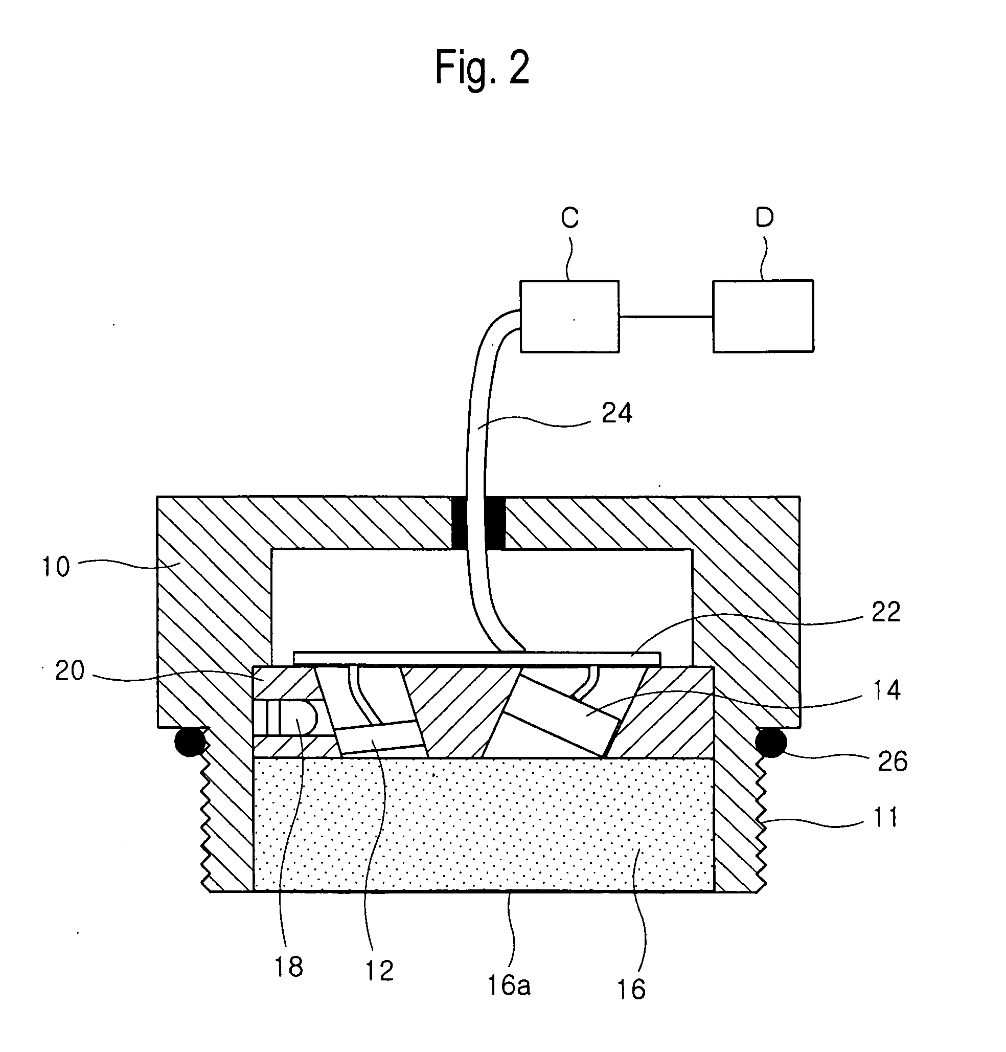
[0039]FIG. 2 is a cross-sectional view showing an oil oxidation monitoring device, which is constructed in accordance with a preferred embodiment of the present invention.

[0040] As shown in the drawing, UV emitting means 12 and color sensing means 14 are provided inside a housing 10. The ultraviolet light from the U emitting means 12 is irradiated into the oil in the oil circulation line or the oil tank through a transparent optical window 16 and induces oil fluorescence. The fluorescence emission of the oil illuminates the color sensing means 14 through the optical window 16. A common available and cheap UV diode with the maximum ...


PUM

PropertyMeasurementUnit
wavelength bandaaaaaaaaaa
wavelengthaaaaaaaaaa

Abstract

There is provided a method and a device of monitoring oil oxidation in real time. The method of the present invention comprises the steps of: irradiating ultraviolet light into oil to be monitored; measuring fluorescence emission intensity of the oil in red, green and blue wavelength bands; determining one value measured in a relatively long wavelength band and the other value measured in a relatively short wavelength band among the fluorescence emission intensity measured in the red, green and blue wavelength bands; calculating a fluorescence emission ratio which is defined as a ratio of the value measured in the relatively long wavelength band to the value measured in the relatively short wavelength band; and monitoring a change in the fluorescence emission ratio. It is then determined whether the fluorescence emission ratio reaches a predetermined critical magnitude. When the fluorescence emission ratio reaches the critical magnitude, the necessity of replacing the oil with new one is indicated.

Description

FIELD OF THE INVENTION [0001] The present invention generally relates to devices for monitoring oil oxidation, and more particularly to a device for monitoring oil oxidation capable of being mounted to mechanical devices so as to detect a power of fluorescence emission of oil in real time as an indication of oil oxidation. BACKGROUND OF THE INVENTION [0002] Chemical and physical analyses of a machine fluid provide information about the condition of the fluid as well as the wear status of the machine using the fluid. Thus, the machine fluid analysis has been widely used for determining lubricant conditions and wear mechanisms in many industries. Further, significant efforts have been made to analyze the condition of the fluid in real time. The real time fluid monitoring mechanism allows the lubricant to be used to its fullest potential with minimized machinery downtime, thereby resulting in increased savings and productivity. [0003] As the oil degrades, the anti-oxidant additive pack...

Claims


Application Information

Patent Timeline
Patent Type & Authority Applications(United States)
IPC IPC(8): G01N21/64
CPCG01N21/6408G01N21/645G01N2021/6421G01N33/2888G01N21/8507A61F11/006A46B15/0057
Inventor KONG, HOSUNGYOON, EUI SUNGHAN, HUNG GUMARKOVA, LYUBOVSEMENYUK, MIKHAILMAKARENKO, VLADIMIR
Owner KOREA INST OF SCI & TECH
Why Eureka
Try Eureka