Flexographic printing plate precursor and imaging method

a flexographic printing plate and precursor technology, applied in the field of laser imageable flexographic printing plate precursors, can solve the problems of difficult visual assessment of the image by users, more of a problem, inferior quality of lithographic printing in this manner, etc., and achieve the effect of high visual contrast and high visual contras

Inactive Publication Date: 2007-08-16
MIRACLON CORP
View PDF18 Cites 39 Cited by
  • Summary
  • Abstract
  • Description
  • Claims
  • Application Information

AI Technical Summary

Benefits of technology

[0023] The present invention also provides an imaged flexographic printing plate having a high visual contrast between the image areas and the non-image background areas. For example, this hig

Problems solved by technology

The quality of the printing in this manner is inferior to processes such as lithography and gravure, but nevertheless it is useful in certain markets.
This can present more of a problem than with offset lithographic plates because the thickness of flexographic printing plates is generally several millimeters instead of fractions of a millimeter.
Thus, the finished plate generally has little or no visual contrast between the image areas and the floor and it is difficult for the user to make any visual assessment of the image because of this lack of contrast.
However, after UV exposure and subsequent wash-out processing, any visual contrast disappears as the overcoat is washed away with the underlying unexposed background areas, so that the imaged flexographic printing plate has no visual contrast between the image and the background.
The UV exposure and washing process still results in unevenness of the image floor.
However, the described plates do not have the elastomeric properties needed for flexographic printing but could be used in letterpress printing.
Thus a letterpress plate would be unsuitable for flexographic printing as it would not give good ink transfer under low pressure and similarly a flexographic plate would be unsuitable for letterpress as the high pressure would distort the softer plate and give very poor image quality with huge dot gain.
Imaging sensitivity is limited by the use of large quantities of block polymers, such as those sold under the trade name of KRATON by Kraton Polymers.
The patent also describes the problem of using carbon black or opaque fillers in that the flexographic printing plate loses its transparency, which complicates mounting

Method used


Image

  • Flexographic printing plate precursor and imaging method
  • Flexographic printing plate precursor and imaging method

Examples


example 1

Flexograihic Printing Plate Precursor

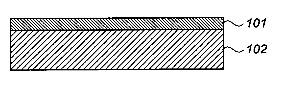
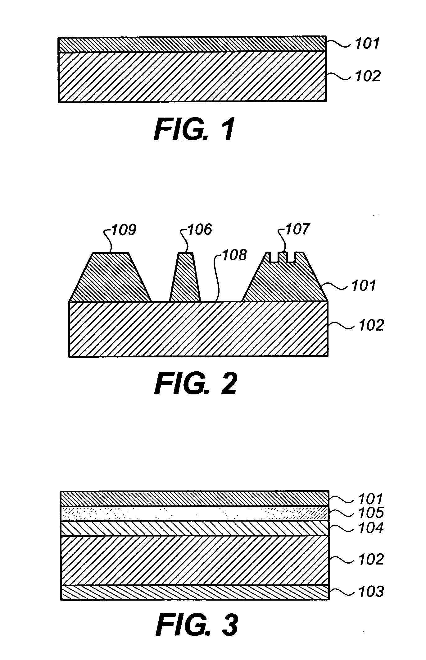
[0071] An embodiment of this invention like that illustrated in FIG. 1 was prepared and imaged in the following manner:

[0072] The following formulation was prepared by adding and mixing the following ingredients in the order shown:

Ebecryl 230 (urethane diacrylate)28.02 gramsEbecryl 1259 (urethane triacrylate) 7.36 gramsIsobornyl acrylate18.49 gramsOleyl alcohol 6.90 gramsIRR 577 (aliphatic monoacrylate) 7.34 gramsPolyester-block polyether diol 6.51 gramsCumene hydroperoxide 2.96 gramsMagnesium oxide14.51 gramsCab-O-Sil M5 7.90 grams

[0073] The resulting white paste was used to form an underlayer (like the underlayer 102 of FIG. 1). The paste was placed into an aluminum mold with a release film above and below it. The bottom release film also contained a filler layer that could be removed when the upper layer 101 formulation (see below) was applied. The mold was sealed with an aluminum lid and it was heated in an oven for 20 minutes at 160° C. ...

example 2

Preferred Flexographic Printing Plate Precursor

[0077] A preferred embodiment of this invention, similar to that illustrated in FIG. 3, was prepared and imaged in the following manner. All quantities are by weight.

[0078] Mixture A:

[0079] The following ingredients were mixed and ball milled for 12 hours to give a fine dispersion of carbon black in the acrylate monomer.

Mogul L carbon black 8.71 gramsIsobornyl acrylate41.29 grams

[0080] Mixture B:

[0081] The following mixture was made up by adding and mixing the ingredients in the order shown:

Ebecryl 230 (urethane diacrylate)11.524 gramsEbecryl 1259 (urethane triacrylate) 1.732 gramsMixture A17.796 gramsCumene hydroperoxide 1.344 gramsPolyisoprene liquid 1.280 grams

[0082] After thorough mixing, 6.320 grams of Cab-O-Sil M5 were added gradually to Mixture B with high speed stirring as the mixture became increasingly higher in viscosity, forming a thick paste.

[0083] A 300 μm poly(ethylene terephthalate) filler sheet was placed at th...

example 3

[0090] Another embodiment of this invention was prepared and imaged in the following manner. All quantities are by weight.

[0091] The following formulations were prepared by adding and mixing the ingredients in the order shown:

[0092] Mixture C:

CN 9170 (Cray Valley)19.4 gramsEbecryl 1259 5.2 gramsIsobornyl acrylate13.1 gramsIRR 577 5.2 gramsPolyester-block-polyether 4.6 gramsLuperox 231XL40 2.1 grams

[0093] Mixture C was in the form of a viscous liquid.

[0094] Mixture D:

Mixture C35.4 gramsOleyl Alcohol 3.5 gramsMagnesium oxide 6.7 gramsCab-O-Sil M5 3.7 grams

[0095] Mixture E:

CN 9170 (Cray Valley)25.84 gramsEbecryl 1259 6.79 gramsIsobornyl acrylate17.05 gramsOleyl Alcohol 6.36 gramsIRR 577 6.77 gramsPolyester-block-polyether   6 gramsMogul L carbon black 7.75 gramsLuperox 231XL4O 2.73 gramsMagnesium oxide13.39 gramsCab-O-Sil M5 7.29 grams

[0096] Mixture D was milled to form a thick white paste by twice passing it through a triple roller mill. It was then used in the manner describ...


PUM

PropertyMeasurementUnit
Lengthaaaaaaaaaa
Thicknessaaaaaaaaaa
Thicknessaaaaaaaaaa

Abstract

A laser imageable flexographic printing plate precursor comprises a thermoset elastomeric upper layer that is at least partially ablatable and comprises a radiation sensitive compound, and a non-ablatable elastomeric underlayer. This flexographic printing plate precursor can be imaged to provide a printing plate that is primarily useful for “high quality” printing because the resulting relief image is generally not greater than 600 μm and has an extremely even “floor”. The imaged flexographic printing plate also can have a high visual contrast between the imaged areas and the non-imaged background areas.

Description

FIELD OF INVENTION [0001] This invention relates to laser-imageable flexographic printing plate precursors and to an imaging process used for producing printing plates that have high visual contrast and can be used to provide high resolution printing. BACKGROUND OF THE INVENTION [0002] Flexography is a method of printing whereby a flexible plate with a relief image is wrapped around a cylinder and its relief image is inked up and the ink is then transferred to a suitable printable medium. The process has mainly been used in the packaging industry where the plates should be sufficiently flexible and the contact sufficiently gentle to print on uneven substrates such as corrugated cardboard as well as flexible materials such as polypropylene film. The quality of the printing in this manner is inferior to processes such as lithography and gravure, but nevertheless it is useful in certain markets. In order to accommodate the various types of printing media, the flexographic plates should...

Claims


Application Information

Patent Timeline
IPC IPC(8): G03C1/00
CPCB41N1/12B41C1/05Y10S430/145Y10S430/146
Inventor KIMELBLAT, JANKIELFIGOV, MURRAYPINTO, YARIV Y.
Owner MIRACLON CORP
Why Eureka
Try Eureka