Method to form upward pointing p-i-n diodes having large and uniform current

a technology of upward pointing pins and diodes, which is applied in the direction of transistors, digital storage, instruments, etc., can solve the problem of difficulty in forming a large population of vertically oriented p-i-n diodes

Inactive Publication Date: 2007-08-16
SANDISK TECH LLC
View PDF24 Cites 256 Cited by
  • Summary
  • Abstract
  • Description
  • Claims
  • Application Information

AI Technical Summary

Problems solved by technology

It has proven difficult to form a large population of vertically oriented p-i-n diodes having a bottom heavily doped p-type region, a middle intrinsic region, and a top heavily doped n-type region with good uniformity of current among the diodes when a voltage above the turn-on voltage is applied.

Method used


Image

  • Method to form upward pointing p-i-n diodes having large and uniform current
  • Method to form upward pointing p-i-n diodes having large and uniform current
  • Method to form upward pointing p-i-n diodes having large and uniform current

Examples


example

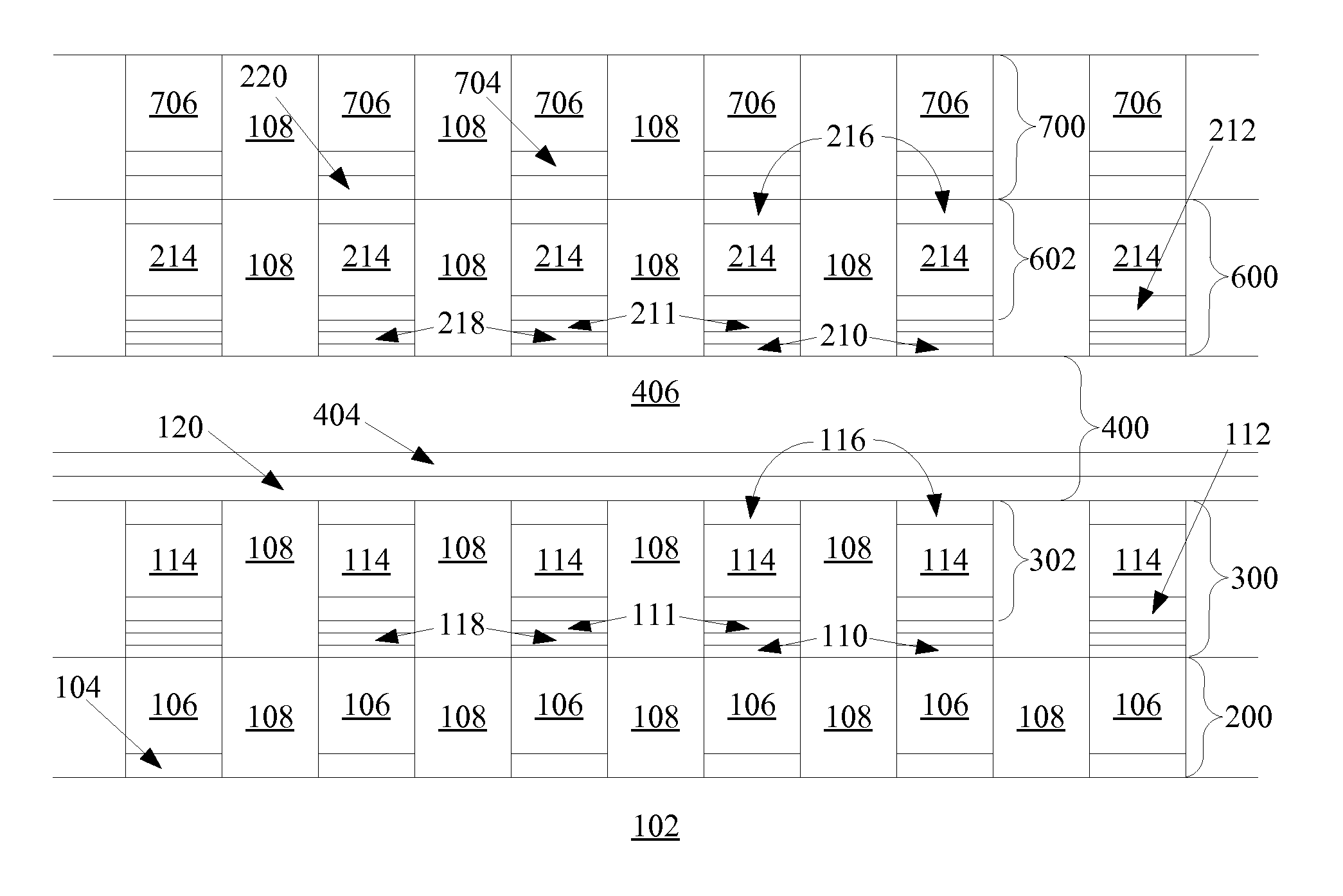
[0036] Turning to FIG. 7a, formation of the memory begins with a substrate 100. This substrate 100 can be any semiconducting substrate known in the art, such as monocrystalline silicon, IV-IV compounds like silicon-germanium or silicon-germanium-carbon, III-V compounds, II-VII compounds, epitaxial layers over such substrates, or any other semiconducting material. The substrate may include integrated circuits fabricated therein.

[0037] An insulating layer 102 is formed over substrate 100. The insulating layer 102 can be silicon oxide, silicon nitride, Si—C—O—H film, or any other suitable insulating material.

[0038] The first conductors 200 are formed over the substrate 100 and insulator 102. An adhesion layer 104 may be included between the insulating layer 102 and the conducting layer 106 to help conducting layer 106 adhere to insulating layer 102. If the overlying conducting layer 106 is tungsten, titanium nitride is preferred as adhesion layer 104. Conducting layer 106 can compris...


PUM


Abstract

A method is disclosed to form an upward-pointing p-i-n diode formed of deposited silicon, germanium, or silicon-germanium. The diode has a bottom heavily doped p-type region, a middle intrinsic or lightly doped region, and a top heavily doped n-type region. The top heavily doped p-type region is doped with arsenic, and the semiconductor material of the diode is crystallized in contact with an appropriate silicide, germanide, or silicide-germanide. A large array of such upward-pointing diodes can be formed with excellent uniformity of current across the array when a voltage above the turn-on voltage of the diodes is applied. This diode is advantageously used in a monolithic three dimensional memory array.

Description

RELATED APPLICATIONS [0001] This application is a continuation-in-part of Herner et al., U.S. patent application Ser. No. 10 / 955,549, “Nonvolatile Memory Cell Without a Dielectric Antifuse Having High- and Low-Impedance States,” filed Sep. 29, 2004, hereinafter the '549 application, which is a continuation-in-part of Herner et al., U.S. Pat. No. 6,952,030, “An Improved Method for Making High-Density Nonvolatile Memory,” hereinafter the '030 patent; which is a continuation of Herner et al., U.S. patent application Ser. No. 10 / 326,470, “An Improved Method for Making High-Density Nonvolatile Memory,” filed Dec. 19, 2002 (since abandoned) and hereinafter the '470 application, all assigned to the assignee of the present invention and hereby incorporated by reference in their entirety [0002] This application is related to Herner, U.S. patent application Ser, No. ______, (Atty. Docket No. SAND-01179US1), Large Array of Upward-Pointing P-I-N Diodes Having Large and Uniform Current”; to Hern...

Claims


Application Information

Patent Timeline
Patent Type & Authority Applications(United States)
IPC IPC(8): H01L21/336G11C7/00G11C11/39G11C17/06G11C17/16G11C29/00H01L21/82H01L27/24H01L29/73H01L45/00
CPCG11C5/02G11C11/39G11C17/06G11C17/16G11C2213/71G11C2213/77H01L27/2481H01L45/04H01L45/1233H01L45/146H01L45/149H01L27/2409H01L27/1021G11C7/00G11C29/00H01L29/0676H01L29/868H01L29/0657H10B63/84H10B63/20H10N70/20H10N70/8845H10N70/8833H10N70/826
Inventor HERNER, S. BRAD
Owner SANDISK TECH LLC
Why Eureka
Try Eureka