
Exhaust heat recovery power generation device and automobile equipped therewith

a technology of exhaust heat recovery and power generation device, which is applied in the direction of generator/motor, electric propulsion mounting, machine/engine, etc., can solve the problems of complicated piping and prevent the exhaust gas from flowing smoothly, and achieve the effect of increasing the thermoelectric conversion efficiency without complicated piping

Inactive Publication Date: 2007-08-23
TOYOTA JIDOSHA KK
View PDF19 Cites 54 Cited by
  • Summary
  • Abstract
  • Description
  • Claims
  • Application Information

AI Technical Summary

Benefits of technology

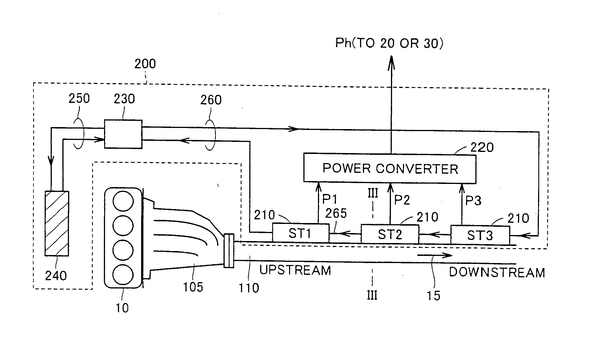
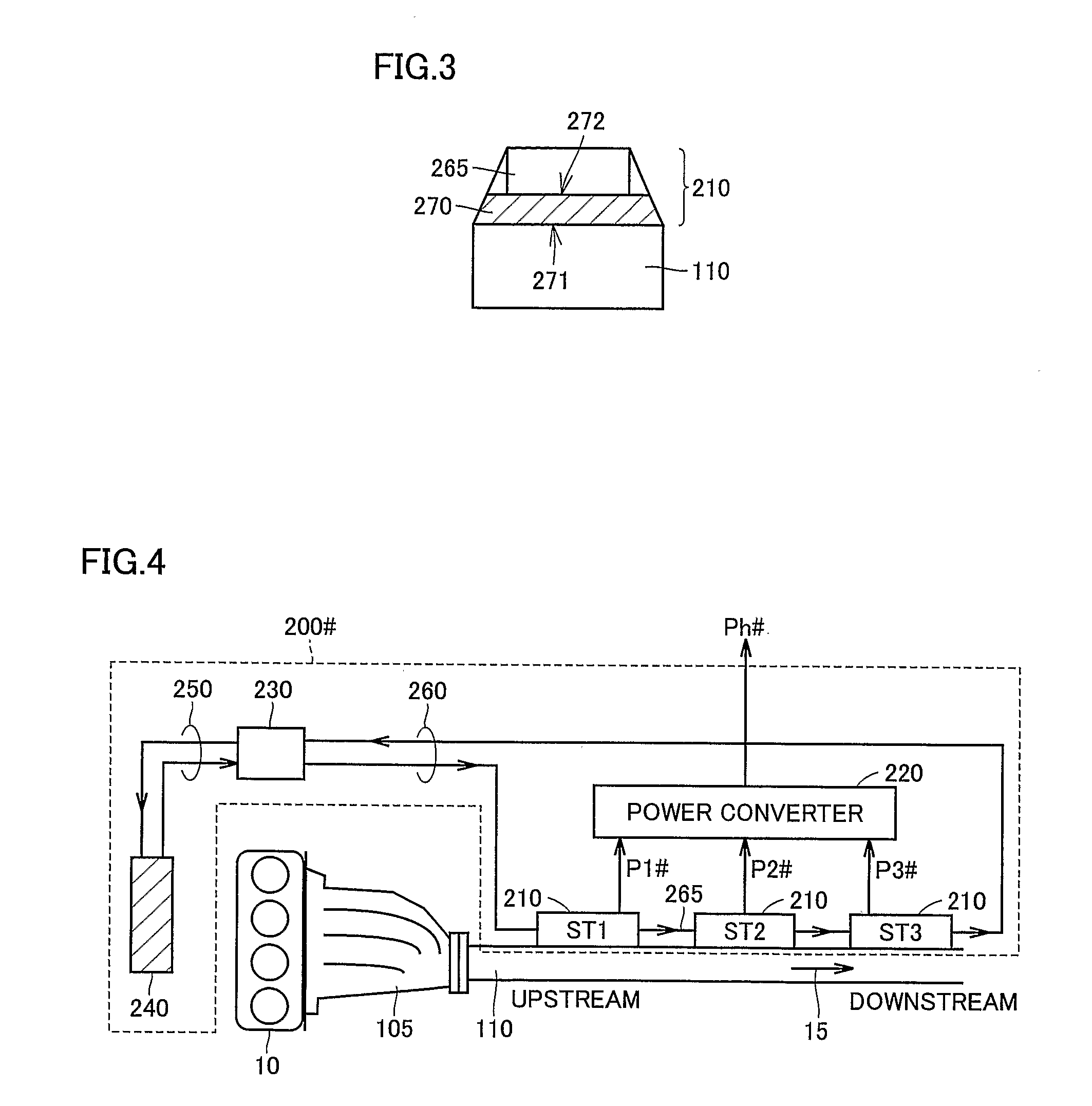
The present invention is an exhaust heat recovery power generation device and automobile equipped with the device. The device includes an exhaust pipe, a cooling pipe, a refrigerant supply unit, and a plurality of thermoelectric power generation units. The plurality of thermoelectric power generation units are attached to the exhaust pipe and the cooling pipe sequentially in a direction in which the exhaust gas flows. The refrigerant supply unit supplies the refrigerant in a direction opposite to the flow of exhaust gas and the cooling pipe. The device allows for efficient recovery of thermal energy from the exhaust gas and improved fuel efficiency of the automobile. The power generated by the device can be used to charge a battery or input to a device generating power to drive a second driving force generation device. The vehicle's energy efficiency can be improved by controlling the operation of the first driving force generation device based on the power output of the exhaust heat recovery power generation device.

Problems solved by technology

However, such a structure, provided with a large number of fins, prevents exhaust gas from flowing smoothly and also entails complicated piping.

Method used


Image

  • Exhaust heat recovery power generation device and automobile equipped therewith
  • Exhaust heat recovery power generation device and automobile equipped therewith
  • Exhaust heat recovery power generation device and automobile equipped therewith

Examples


Embodiment Construction

[0027] Hereinafter the present invention in an embodiment will be described more specifically with reference to the drawings. Throughout the specification, identical or like components are identically denoted.

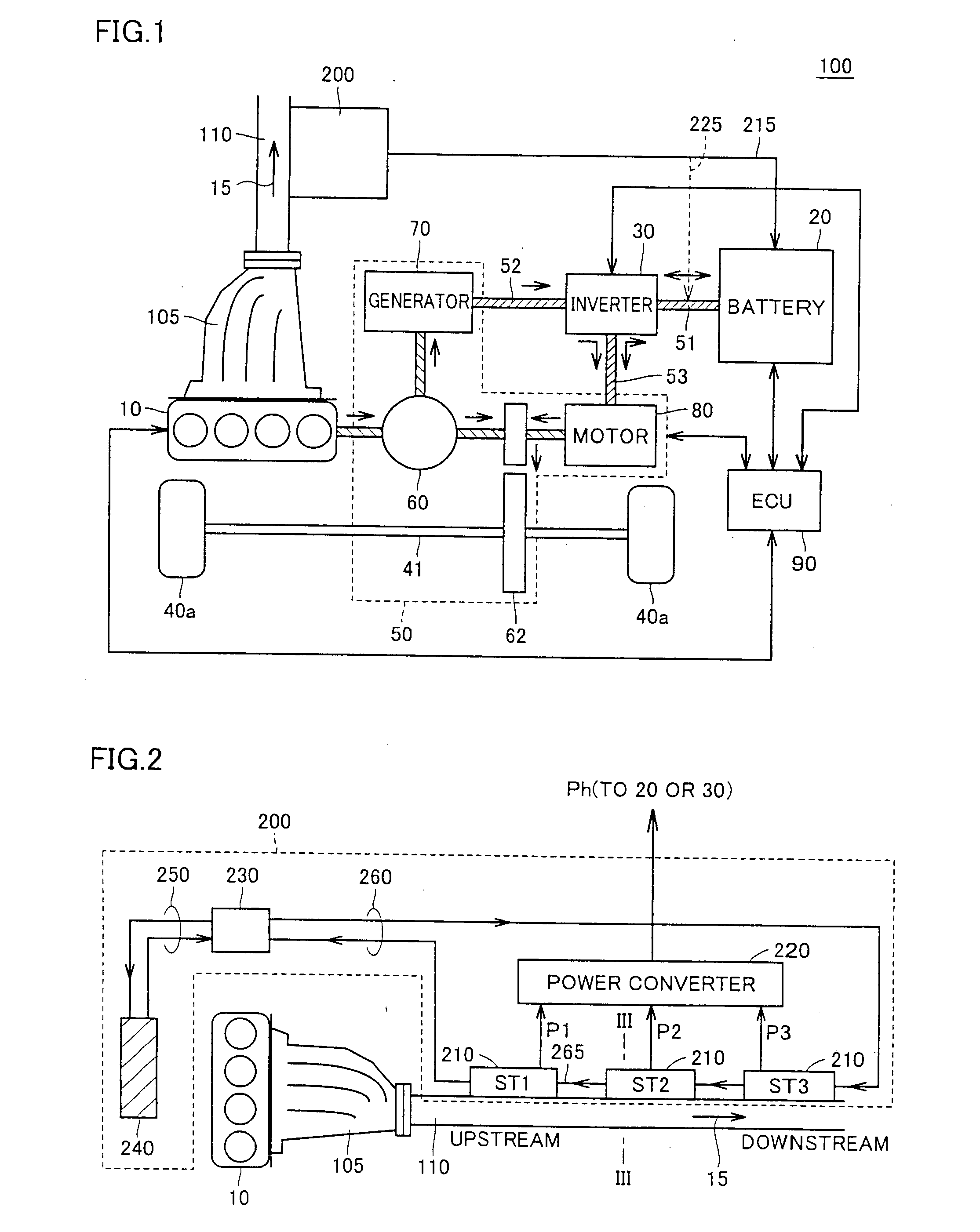
[0028]FIG. 1 is a block diagram generally showing a configuration of a hybrid system 100 of an automobile equipped with the present exhaust heat recovery power generation device.

[0029] With reference to FIG. 1, the present embodiment's hybrid system 100 includes an engine 10, a battery 20, an inverter 30, a wheel 40a, a transaxle 50, an electric control unit (ECU) 90, an exhaust manifold 105, an exhaust pipe 110, and an exhaust heat recovery power generation device 200.

[0030] Engine 10 uses gasoline or similar fuel's combustion energy as a source to generate force driving wheel 40a. More specifically, engine 10 corresponds to a “first driving force generation device” of the present invention. Furthermore, engine 10 also acts as a “heat source” in the present invention. Exhau...


PUM


Abstract

An engine exhausts gas which is in turn exhausted through an exhaust pipe in a prescribed direction. A cooling water pump supplies cooling water to circulate a refrigerant through each of cooling water circulation paths. The cooling water circulation path includes a cooling water pipe arranged along the exhaust pipe to pass the cooling water. At stacks a plurality of thermoelectric power generation elements are attached to the exhaust pipe and the cooling water pipe successively in a direction from the upstream toward downstream of the exhaust gas. The cooling water pipe and the exhaust pipe pass the cooling water and the exhaust gas, respectively, in opposite directions so that the downstream stack has an increased difference in temperature between the exhaust pipe and the cooling water pipe, and the stacks provide power outputs having a reduced difference, and hence an increased total power output. Thus an exhaust heat recovery power generation device can provide increased thermoelectric conversion efficiency without complicated piping.

Description

TECHNICAL FIELD [0001] The present invention relates to exhaust heat recovery power generation devices and particularly to exhaust heat recovery power generation devices receiving thermal energy of exhaust gas from a heat source such as an engine of a vehicle and converting the thermal energy to electrical energy, and automobiles equipped therewith. BACKGROUND ART [0002] To achieve energy conservation, exhaust heat recovery power generation devices have conventionally been proposed that employ a thermoelectric conversion element to convert thermal energy contained in gas exhausted for example from automobile engines, factories and the like to electrical energy to effectively use the energy, as disclosed for example in Japanese Patent Laying-Open No. 61-2540 82. In particular, there have been proposed a configuration mounting such an exhaust heat recovery power generation device in a hybrid automobile to prevent reduced energy efficiency when an operation recovering waste energy has ...

Claims


Application Information

Patent Timeline
Patent Type & Authority Applications(United States)
IPC IPC(8): H01L35/28B60K1/02B60K6/445B60L50/16B60W10/26F01N5/02F02G5/02F02G5/04H01L35/30H02N11/00
CPCB60K1/02B60K6/365B60K6/442B60K6/445B60K6/543F01N13/009B60W10/26F01N5/025Y02T10/6234Y02T10/16Y02T10/6239B60K2001/0411Y02T10/12Y02T10/62F02G5/02F01N5/02
Inventor TAGUCHI, TOMONARI
Owner TOYOTA JIDOSHA KK
Learn More