Method and apparatus for high transfer efficiency electrostatic spray

a technology of electrostatic spray and transfer efficiency, which is applied in the direction of electrostatic spraying apparatus, lighting and heating apparatus, burners, etc., can solve the problems of reducing the efficiency of electrostatic charging, complex nozzle assemblies for such spraying, and unsatisfactory high-speed spray of liquid droplets or air, etc., and achieves relatively low cost of adding an electrode and an unregulated low-power converter

Inactive Publication Date: 2007-08-23
BIOMED PROTECT
View PDF31 Cites 40 Cited by
  • Summary
  • Abstract
  • Description
  • Claims
  • Application Information

AI Technical Summary

Benefits of technology

[0013] In this process, the charge on the sprayed particles can have either a polarity that is opposite to the voltage, i.e., electrical potential, on the electrode or the same polarity as the voltage on the electrode according to the proximity of the electrode to the spray of droplets. When spraying a highly or moderately conductive liquid, according to a preferred embodiment of this invention, the electrode is mounted on a non-conducting electrode holder. An electrically conducting cable covered or coated with electrical insulation connects the electrode to the high voltage (HV) power supply. This cable is called the HV cable. The electrode holder is surrounded by or mounted on an electrically insulating concave cup. The open end of the cup is situated away from the direction of the spray so that the insulating cup maintains a dry surface either on a portion of the electrode holder or on its mounting to the sprayer so that a significant electric current will not leak from the electrode to a grounded surface via the wetted surfaces and cause a significant drop in the voltage on the electrode. Additionally, the HV cable either passes through a hole in the cup, as described by Wang et al., with means for sealing the interface between the cup and the insulation of the HV cable, e.g., sealant glue, or the HV cable passes around the side of the cup and then into the cup interior so that a portion of its insulation remains protected from spray and maintains a sufficiently dry surface to prevent unacceptable electrical leakage current or an electrical short circuit.
[0014] The electrode and nozzle are contained within a housing that has an exit hole or slot through which the directed spray exits. The housing protects the operator or other persons from inadvertently contacting the high voltage electrode and that also provides a means of collecting small diameter charged particles that can be attracted back to the sprayer. The housing may be of electrically conductive, e.g., metal, or resistive material, e.g., conductive plastic, or it may be covered either entirely or in part by a conductive or resistive film, coating, tape, or wires. As the spray of droplets exit the sprayer housing, those particles with insufficient velocity to travel to a target surface may be attracted back to the sprayer. These droplets are termed backspray. Because of the conductivity of the liquid, a very slight partial coating of the housing by the backspray can make the housing sufficiently conducting so that a path to ground is provided and the charges of the droplets of the backspray deposited on the housing will be carried to ground. In a preferred embodiment, the housing is made of plastic and covered with resistive tape around part of its exterior surface on each side of the exit slot of the housing. The tape makes contact with a wire that electrically connects to the ground connection of the nozzle.
[0018] The spray nozzle can be any airless gun where the liquid is atomized by the hydraulic pressure, provided that the spray nozzle is electrically conductive and grounded. In a preferred embodiment, the nozzle produces a flat-fan or sheet spray. Instability of the liquid jet exiting from such a nozzle causes transverse oscillations that lead to jet breakup into droplets in a short axial distance. Instabilities may include flapping (“flag”) modes, longitudinal modes, and transverse “rolling” modes. Such jet breakup can provide sufficient transverse velocity to the smaller droplets in the spray so that they may be removed from the principal part of the spray. The nozzle can be mounted on a hand held spray gun, which can be electrically conductive or insulating. The spray gun may have an on-off valve. The electrical connection between the nozzle and ground can be achieved with an electric wire or simply through the liquid path, if the liquid's resistivity is not very high. The electrostatic spray gun in this invention is safe because the spray gun and the liquid path are grounded and, when a short circuit occurs, the output voltage of the converter will quickly drop to the same level as the input to avoid electric shock.
[0020] Surrounding the manifold, nozzles, and electrode is a housing that has the electrical properties described above and that also has an opening so that the sprayed particles can exit the assembly with minimal interception of particles from the spray by the housing.
[0021] Because this electrostatic method can be applied with most of the existing commercial non-electrostatic spray guns, and because the cost of adding an electrode and an unregulated low-power converter is relatively low, the electrostatic method in this invention is much more economical than those currently available.

Problems solved by technology

There are numerous uses for spraying an electrostatically charged aerosol of electrically conducting liquid droplets for which high transfer efficiency is desirable and a high velocity spray of liquid droplets or air is not desirable.
The gas jet in such a situation may aid in reducing the number of charged aerosol droplets that reach the nearby electrode and comprise a leakage current that reduces the efficiency of the electrostatic charging.
Moreover, the nozzle assemblies for such spraying often are intricate as both compressed gas and the liquid must be supplied to the spray nozzle.
However, for less viscous liquids and those of moderate or high electrical conductivity, such as aqueous based disinfectants, decontaminants, cleaning solutions, or fertilizers, such a scheme can produce a large proportion of small diameter droplets that may constitute a mist and do not transfer well to a target surface, and the backward attraction of such small droplets to the sprayer may present a safety problem for an operator if the sprayer is hand held, and the small droplets may coat the electrical insulation of the HV leads in the vicinity of the nozzle or electrode and result in arcing, current leakage, or an electrical short circuit.

Method used


Image

  • Method and apparatus for high transfer efficiency electrostatic spray
  • Method and apparatus for high transfer efficiency electrostatic spray
  • Method and apparatus for high transfer efficiency electrostatic spray

Examples


Embodiment Construction

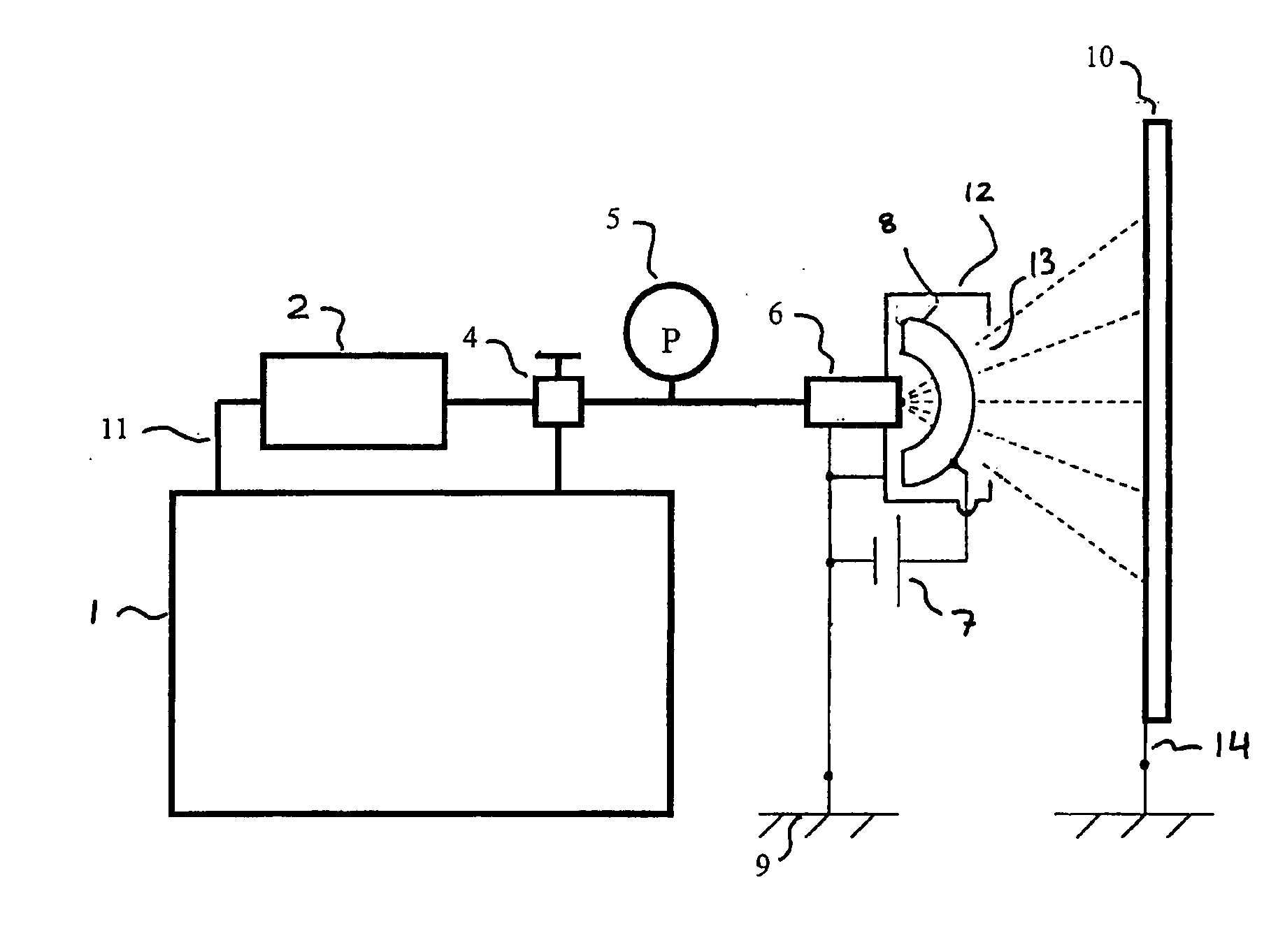
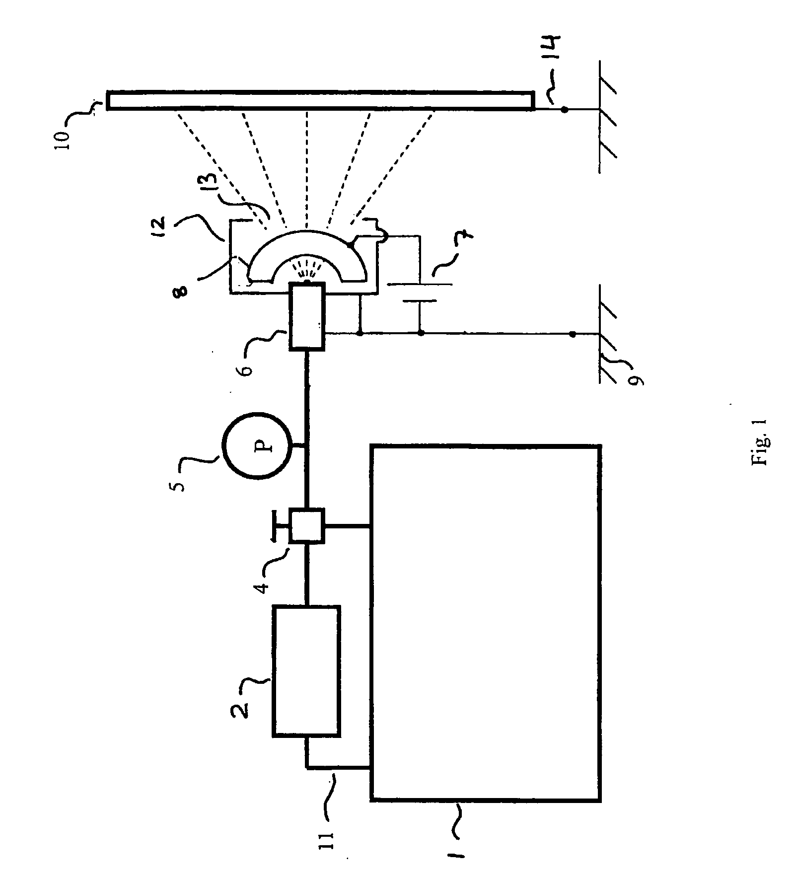
[0046] An apparatus, an electrostatic spraying system, for electrostatic spray in accordance with the principles of the present invention is illustrated schematically in FIG. 1. The liquid or particles to be sprayed are contained in reservoir 1, which is connected by a tube 11 to a pump 2. The spray pressure is controlled by a regulator 4 and displayed by a pressure gage 5. The spray gun 6 is an integration of a valve, a connection for liquid supply, and a nozzle from which a liquid jet emanates and then disintegrates, i.e., liquid jet breaks up and separates into particles (droplets). The electrostatic charge is induced from the ground 9 through the spray gun onto the particles by the high voltage on the electrode assembly 8. The high voltage is generated by a high-voltage (HV) converter 7 which converts a low voltage DC signal into high-voltage DC output. The HV potential can be either positive or negative polarity. The particles are sprayed toward a target object 10, e.g. a wall ...


PUM


Abstract

A method of spraying an aerosol spray, comprising providing a grounded nozzle and an electrode separated by a predetermined distance; placing the electrode at a high electrical potential relative to the nozzle, thereby creating an electric field between the nozzle and the electrode; ejecting a liquid from the nozzle towards the electrode to atomize the ejected liquid into aerosol droplets or particles, so that in the applied electric field between the nozzle and the electrode the aerosol droplets or particles obtain an induced electric charge; and forming a directed spray of aerosol droplets or particles having a desired shape and with sufficient momentum and electric charge so that the directed spray of aerosol droplets or particles is deposited on a target.

Description

CROSS-REFERENCE TO RELATED APPLICATIONS [0001] This application is a continuation-in-part of copending U.S. application Ser. No. 10 / 632,891 (incorporated by reference herein), filed Aug. 1, 2003, which in turn claims priority to U.S. Provisional Application No. 60 / 401,563 filed Aug. 6, 2002.STATEMENT REGARDING FEDERALLY SPONSORED RESEARCH OR DEVELOPMENT [0002] This work was part of a project supported by the Technical Support Working Group under contract DAAD05-02-C-0017. The Federal Government retains Unlimited Rights, including the right to use, modify, perform, display, release, or disclose technical data in whole or in part, in any manner or for any purpose whatsoever, and to have or authorize others to do so in the performance of a Government Contract.BACKGROUND OF THE INVENTION [0003] 1. Field of the Invention [0004] This invention relates to electrostatic-spray methods and apparatus, and in particular to methods of and apparatus for adding electric charges onto liquid to impr...

Claims


Application Information

Patent Timeline
Patent Type & Authority Applications(United States)
IPC IPC(8): B05B5/00B05B5/025
CPCB05B5/025
Inventor GOLDEN, JEFFRYKOCHER, CHRISTOPHER G.HANLON, MATTHEW A.
Owner BIOMED PROTECT
Why Eureka
Try Eureka