Variable passive components with high resolution value selection and control

a passive component and variable technology, applied in the field of variable passive components with high resolution value selection and control, can solve the problems of large number of unused components, the effect of techniques generally limited to specific types of components, and the characteristics of fet switches

Inactive Publication Date: 2007-08-23
MASHHOON HAMID R +1
View PDF12 Cites 3 Cited by
  • Summary
  • Abstract
  • Description
  • Claims
  • Application Information

AI Technical Summary

Benefits of technology

[0029] In one or more embodiments, the present system includes external drive circuitry for high current applications, including one or more output current amplifiers having both differential inputs and differential outputs.
[0030] In one or more embodiments of the present system, the fixed value passive component is a distributed structure such as a transmission line, resonant cavity, slotted line, stub tuner, waveguide or antenna.
[0031] In one or more embodiments of the present system, more than one DAC controls current injection or removal from a single pair of node

Problems solved by technology

The effectiveness of the techniques is generally limited to specific types of components over a limited range of operating conditions, such as frequency or power level.
A switched resistor network is used with control FETs such that turning one or more FETs “on” places resistors in parallel, reducing the effective resistive value of the combination.
Among the undesirable characteristics of this approach are the large number of unused components and the characteristics of the FET switches.
When a value has been selected, there are typically many unused components.
This is typically not a major issue for an integrated resistor network but switched capacitor networks can require discrete capacitors to realize large values, adding cost and using circuit board area that could be used for functioning circuitry.
The switch FETs also can present significant problems.
If the FETs are enlarged to reduce resistance, they consume greater area.
Either way, there is an incentive to minimize the number of

Method used


Image

  • Variable passive components with high resolution value selection and control
  • Variable passive components with high resolution value selection and control
  • Variable passive components with high resolution value selection and control

Examples


Embodiment Construction

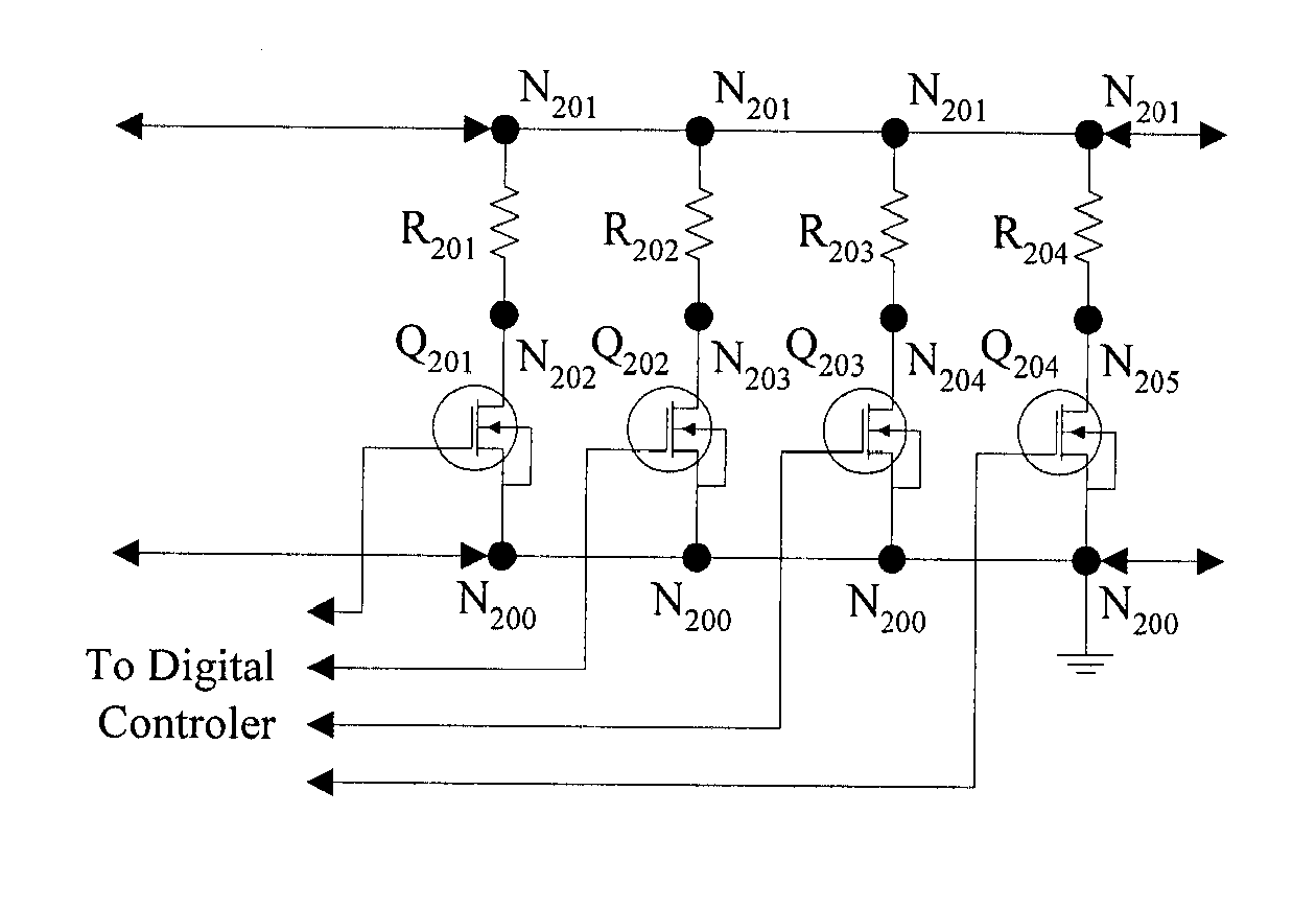
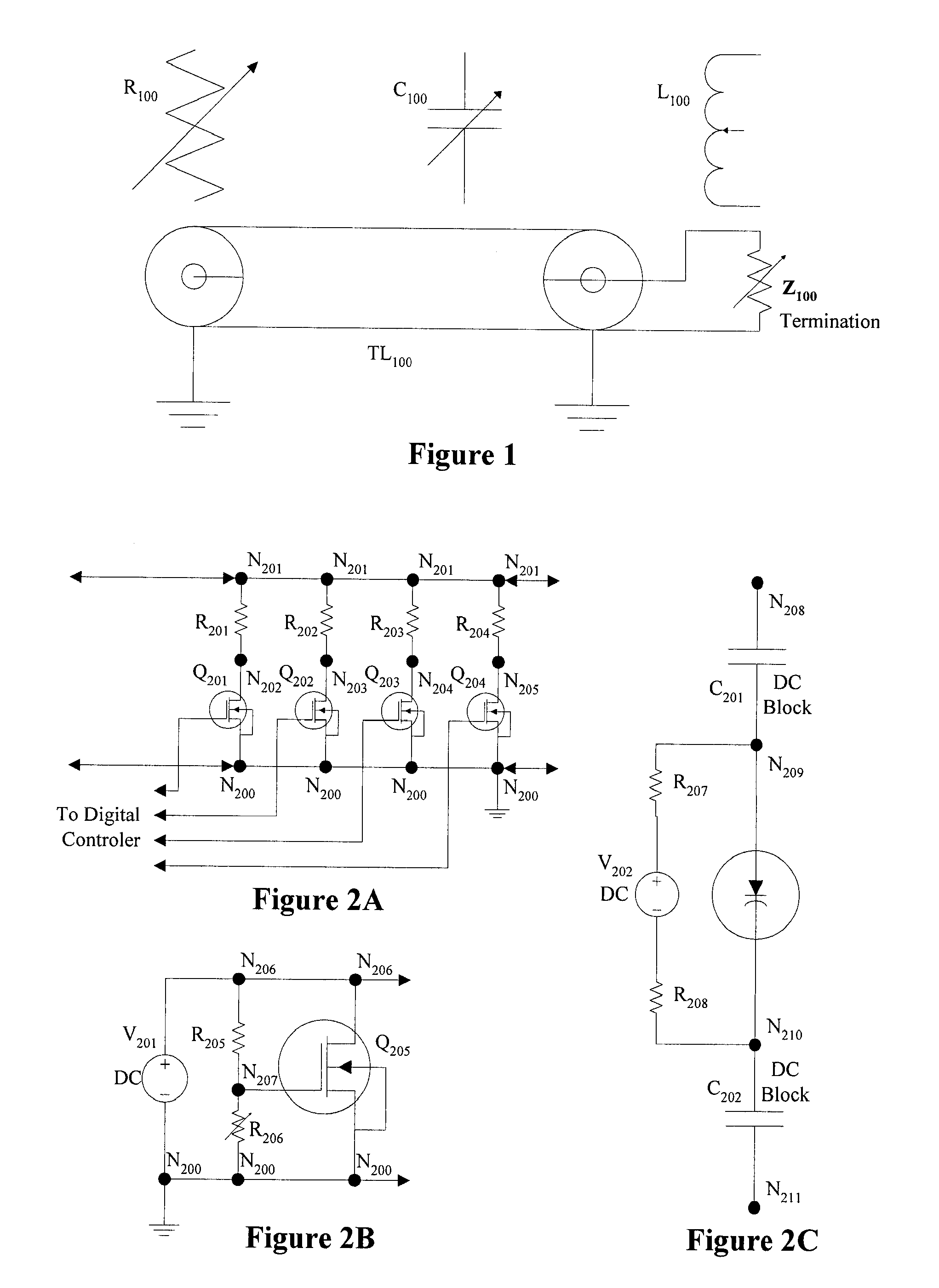
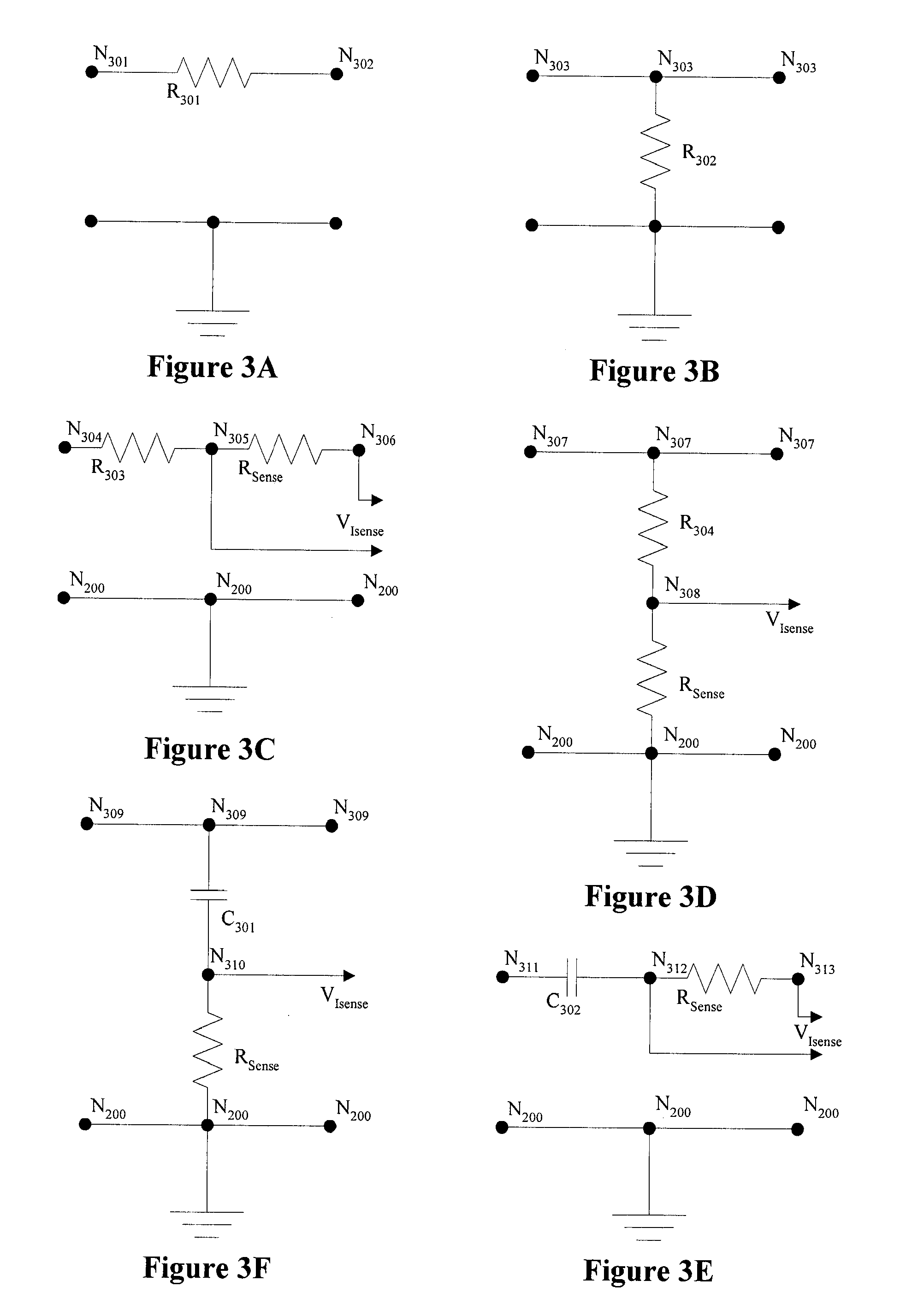
[0063] The present system is directed to variable passive components with high-resolution, digital value selection and control. In the following description, numerous specific details are set forth to provide a more thorough description of embodiments of the system. It is apparent, however, to one skilled in the art, that the system may be practiced without these specific details. In other instances, well known features have not been described in detail so as not to obscure the system. Except as noted herein, common components and connections, identified by common reference designators function in like manner in each circuit.

[0064] The present system is a digital-to-analog converter circuit that provides the capability to dynamically vary the apparent value of passive components to the circuitry to which they are coupled in a wide range in analog and mixed signal electronic circuits. The term “fixed value” refers to does not imply that the value of the component does not vary with ...


PUM


Abstract

The present system provides a method for varying the value of passive components in electronic circuits. Passive components can range from basic resistors, capacitors, and inductors to complex, structures such as transmission lines and resonant cavities. Value selection and variation can either be dynamically performed during circuit operation or as a one-time part of the manufacturing process as determined by the requirements of the specific application. A digital-to-analog converter (DAC) circuit is used to input value selection data digitally, and control value selection with value resolution dependent on the resolution of the DAC. An alternate embodiment is provided for high frequency operation.

Description

CROSS-REFERENCE TO RELATED APPLICATIONS [0001] This application claims the benefit of U.S. provisional patent application No. 60 / 734,516, filed Nov. 7, 2005, which is herein incorporated by reference in its entirety.BACKGROUND [0002] A portion of the disclosure of this patent document contains material that is subject to copyright protection. The copyright owner has no objection to the facsimile reproduction by anyone of the patent document or the patent disclosure, as it appears in the Patent and Trademark Office patent files or records, but otherwise reserves all copyright rights whatsoever. [0003] 1. Field [0004] The present system relates to the field of variable, passive, electronic components. [0005] 2. Background Art [0006] Throughout the history of electronics, the inherent characteristics and consequences associated with the presence of fixed value passive components have impacted circuit performance. The characteristics include component tolerances, tolerance build-up, the...

Claims


Application Information

Patent Timeline
IPC IPC(8): H03K5/01
CPCH03F1/08H03H11/48H03F1/56H03F3/343H03F3/4508H03F3/45475H03F2200/222H03F2200/321H03F2200/387H03F2200/91H03F2203/45031H03F2203/45136H03F2203/45352H03H7/25H03H7/40H03H11/30H03F1/3211H03H11/481H03H11/53H03M1/66
Inventor WASHBURN, ROBERTMCCLANAHAN, ROBERT
Owner MASHHOON HAMID R
Why Eureka
Try Eureka