Honeycomb filter

Inactive Publication Date: 2007-08-23
NGK INSULATORS LTD
View PDF3 Cites 29 Cited by
  • Summary
  • Abstract
  • Description
  • Claims
  • Application Information

AI Technical Summary

Benefits of technology

[0014]Since a predetermined range from the outlet side end portion in a central portion of a honeycomb filter is made a catalyst-unloaded region (central unloaded portion), a predetermined range from the outlet side end portion of the peripheral portion (region of ⅔ or less of average length in the central unloaded portion) is made a catalyst-unloaded region (outer peripheral unloaded portion), and the other remaining range is made a catalyst-loaded region; combustion of PM trapped in the catalyst-unloaded region is slow in comparison with the catalyst-loaded region. Accordingly, a heat generation amount per unit time

Problems solved by technology

Since the DPF is finally clogged unless trapped PM is removed, the filter needs regeneration.
Thus, in the case that PM trapped by the DPF carrying a catalyst is removed by combustion with exhaust gas, there arise problems of catalyst deterioration, crack generation in a partition wall, and melting of a partition wall in the vicinity of an end portion (outl

Method used


Image

  • Honeycomb filter
  • Honeycomb filter
  • Honeycomb filter

Examples


example 1

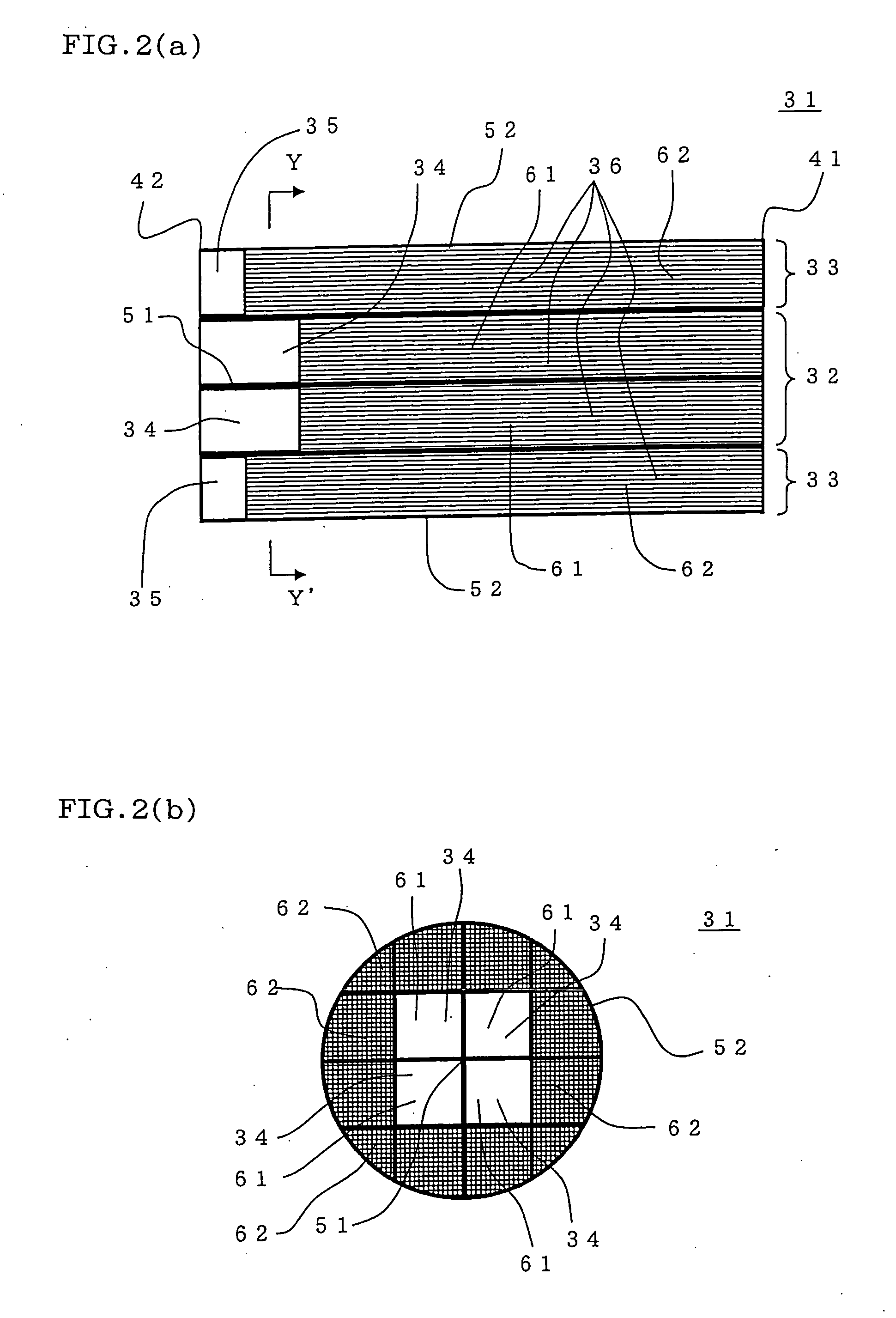
[0050]There was manufactured a honeycomb filter composed of 16 (4×4) segments and having a central portion formed by four quadratic prism-shaped segments as shown in FIGS. 2(a) and 2(b).

[0051]As a forming material, SiC powder and metal Si powder were mixed at a mass ratio of 80:20 to give a mixture. To the mixture were added starch and foaming resin as pore formers and further added methyl cellulose, hydroxypropoxylmethyl cellulose, a surfactant, and water to obtain clay having plasticity.

[0052]The obtained clay was subjected to extrusion forming to obtain 16 segments constituting a honeycomb filter shown in FIGS. 2(a) and 2(b). For each segment, extrusion forming was performed using a die which gives a cell structure of 12 mil / 300 cpsi (“0.3 mm” / “46.5 cells / cm2”). The honeycomb-shaped segments were dried and fired to obtain honeycomb segments.

[0053]Next, a catalyst was loaded on the honeycomb segments and dried. The catalyst used was alumina, platinum, and ceria. The total amount o...

example 2

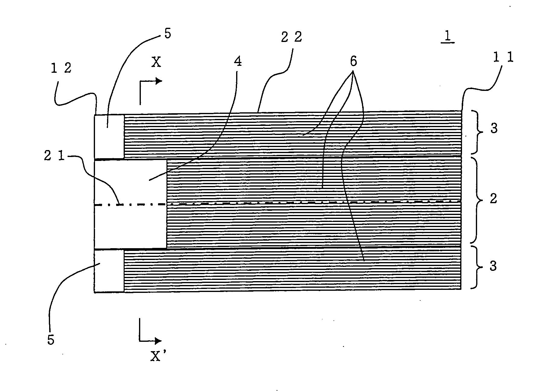
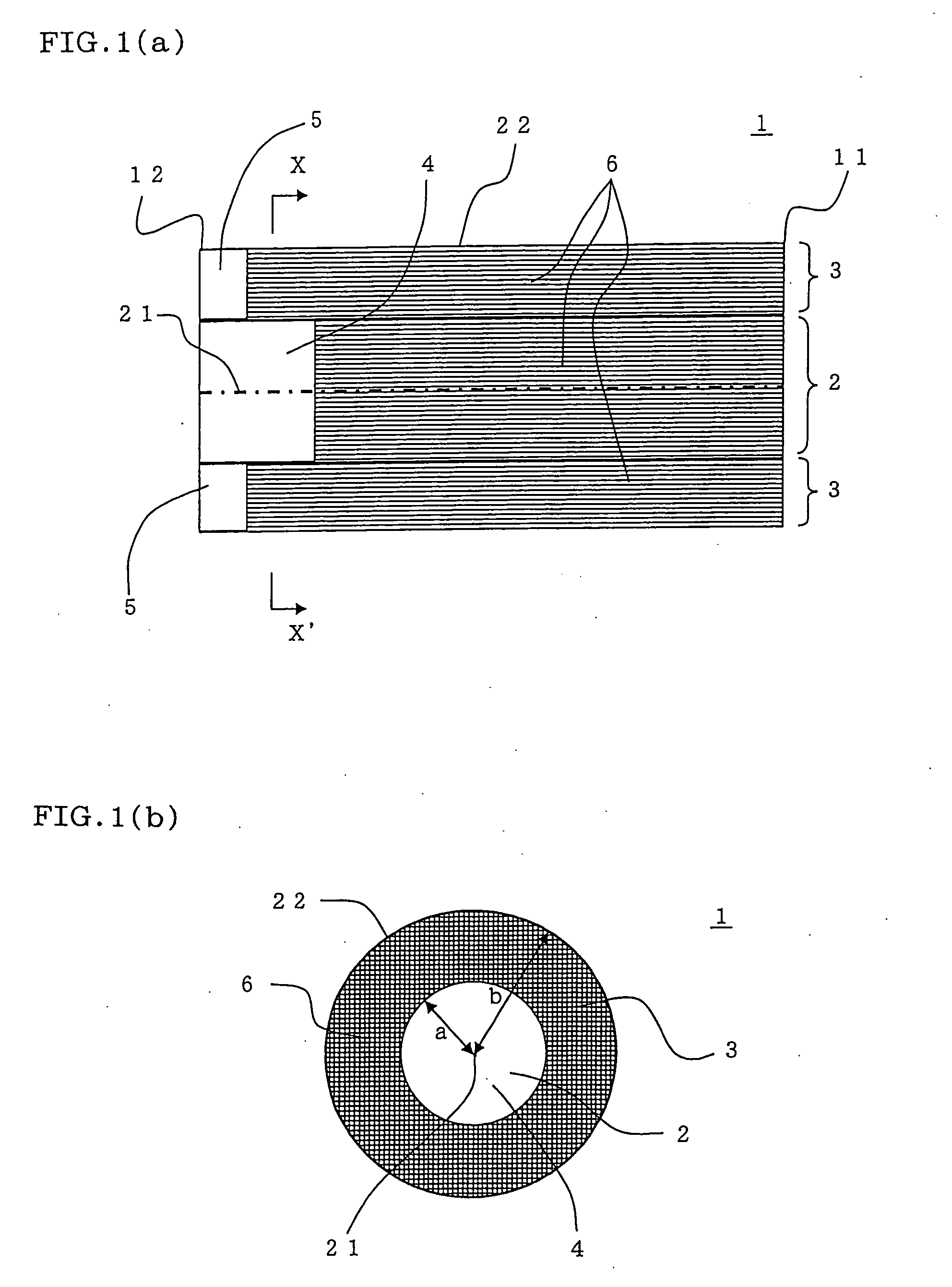
[0055]As shown in FIGS. 3(a) and 3(b), the catalyst was loaded on the whole honeycomb segments (100% of the whole length) lest the outer peripheral unloaded portion therein should be formed when the catalyst is loaded on the 12 segments (outer peripheral segments) 72 constituting the outer peripheral portion 71. Except for this, a honeycomb filter 101 was obtained in the same manner as in Example 1. FIG. 3(a) is a cross-sectional view schematically showing a honeycomb filter of Example 2, and FIG. 3(b) is a x-x′ cross-sectional view of FIG. 3(a).

example 3

[0056]After 16 honeycomb segments were obtained by firing as in Example 1, before the catalyst was loaded on each honeycomb segment, 16 honeycomb segments were joined to obtain a cylindrical honeycomb structure. After that, when the honeycomb structure is immersed in catalyst-loaded liquid, the central axis of the honeycomb structure is inclined from the direction perpendicular to the liquid surface of the catalyst-loaded liquid to load the catalyst with rotating the honeycomb filter around the central axis during immersion to give a honeycomb filter 102. This forms the end face on the inlet side end portion 83 side in a conical shape in a catalyst-unloaded region including the central unloaded portion 81 and the outer peripheral unloaded portion 82 as shown in FIGS. 4(a) and 4(b). The apex of the cone on the end face side formed in a conical shape of the catalyst-unloaded region was located at the site of 30% of the whole length from the outlet side end portion 84. The average leng...


PUM

PropertyMeasurementUnit
Massaaaaaaaaaa
Radiusaaaaaaaaaa
Efficiencyaaaaaaaaaa

Abstract

A honeycomb filter 1 includes: partition walls separating and forming a plurality of cells extending in a direction of a central axis 21, and a catalyst loaded on the partition wall. A region (central unloaded portion) 4 from one end portion (outlet side end portion) 12 in the direction of the central axis to at least ½ of length in the direction of the central axis in a central portion 2 including the central axis 21 and excluding an outer periphery 22 is a catalyst-unloaded region, a region (outer peripheral unloaded portion) 5 from the outlet side end portion 12 to ⅔ or less of length in the direction of the central axis in the central unloaded portion 4 is a catalyst-unloaded region, and a portion excluding the central unloaded portion 4 and the outer peripheral unloaded portion 5 from the whole is a catalyst-loaded portion. The honeycomb filter can inhibit catalyst deterioration, occurrence of crack, and melting and raise regeneration efficiency.

Description

BACKGROUND OF THE INVENTION AND RELATED ART STATEMENT[0001]The present invention relates to a honeycomb filter. More particularly, the present invention relates to a honeycomb filter capable of inhibiting catalyst deterioration, occurrence of crack, and melting upon regeneration of the honeycomb filter and raising regeneration efficiency.[0002]There is used a honeycomb filter of ceramic in order to trap dust and other particulate matter contained in an exhaust gas from automobiles, incineration exhaust gas generating upon incineration of waste, or the like. A diesel particulate filter (hereinbelow referred to as a “DPF”) is used in order to effectively remove, particularly, particulate matter (hereinbelow sometimes referred to as “PM”) such as soot discharged from an internal combustion engine.[0003]Since the DPF is finally clogged unless trapped PM is removed, the filter needs regeneration. Regeneration of the filter can generally be performed by heating the DPF to combust PM. For ...

Claims


Application Information

Patent Timeline
IPC IPC(8): B01D50/00B01D53/34
CPCB01D46/0063B01D46/2455B01D46/2459B01D46/2466B01D53/944F01N2340/00B01D2046/2496B01D2258/012B01J35/04F01N3/035F01N2330/06B01D2046/2481B01D46/249B01D46/2498B01D46/84B01D46/2482B01D46/2478F01N3/022B01D46/2496
Inventor MIZUTANI, TAKASHI
Owner NGK INSULATORS LTD
Why Eureka
Try Eureka