Lesion assessment by pacing

a technology of lesion assessment and pacing, which is applied in the field of lesion assessment by pacing, can solve the problems of difficult to determine the proper dosage of energy, arrhythmias may persist or return, and dangerous damage to the tissue at and around the ablation site, so as to mitigate the danger of excessive ablation

Active Publication Date: 2007-08-23
BIOSENSE WEBSTER INC
View PDF39 Cites 67 Cited by
  • Summary
  • Abstract
  • Description
  • Claims
  • Application Information

AI Technical Summary

Benefits of technology

[0011] A safe, simple method for monitoring ablation progress in near real time is provided by disclosed embodiments of the invention, in which capture of a pacing signal is evaluated while ablation energy is concurrently directed to a target site. Using this technique, a practitioner can determine when a sufficient lesion has been created without interrupting the ablation procedure. The same catheter and electrode that are used for ablation are simultaneously used to test pacing capture. According to aspects of the invention, the practitioner immediately knows when to stop ablating, indicated by loss of capture of a pacing signal at a predetermined maximum voltage. Thus, the danger of excessive ablation is mitigated.

Problems solved by technology

It is often difficult to determine the proper dosage of energy, e.g., radiofrequency energy, that should be applied in an ablation procedure in order to achieve the desired result.
When the dosage is insufficient, the non-conducting lesion does not extend deeply enough through the heart wall to disrupt the abnormal conduction, so that arrhythmia may persist or return after the procedure is completed.
On the other hand, excessive dosage may cause dangerous damage to the tissue at and around the ablation site.

Method used


Image

  • Lesion assessment by pacing
  • Lesion assessment by pacing
  • Lesion assessment by pacing

Examples


embodiment 1

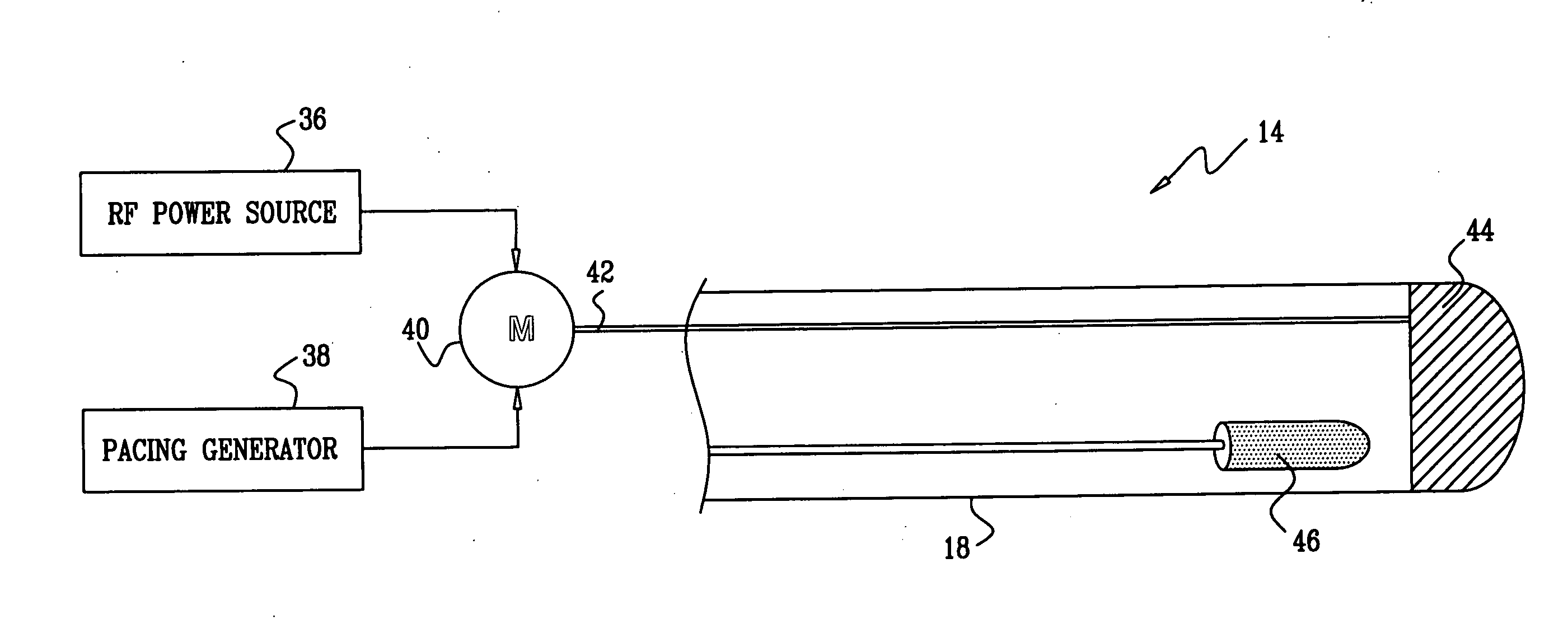
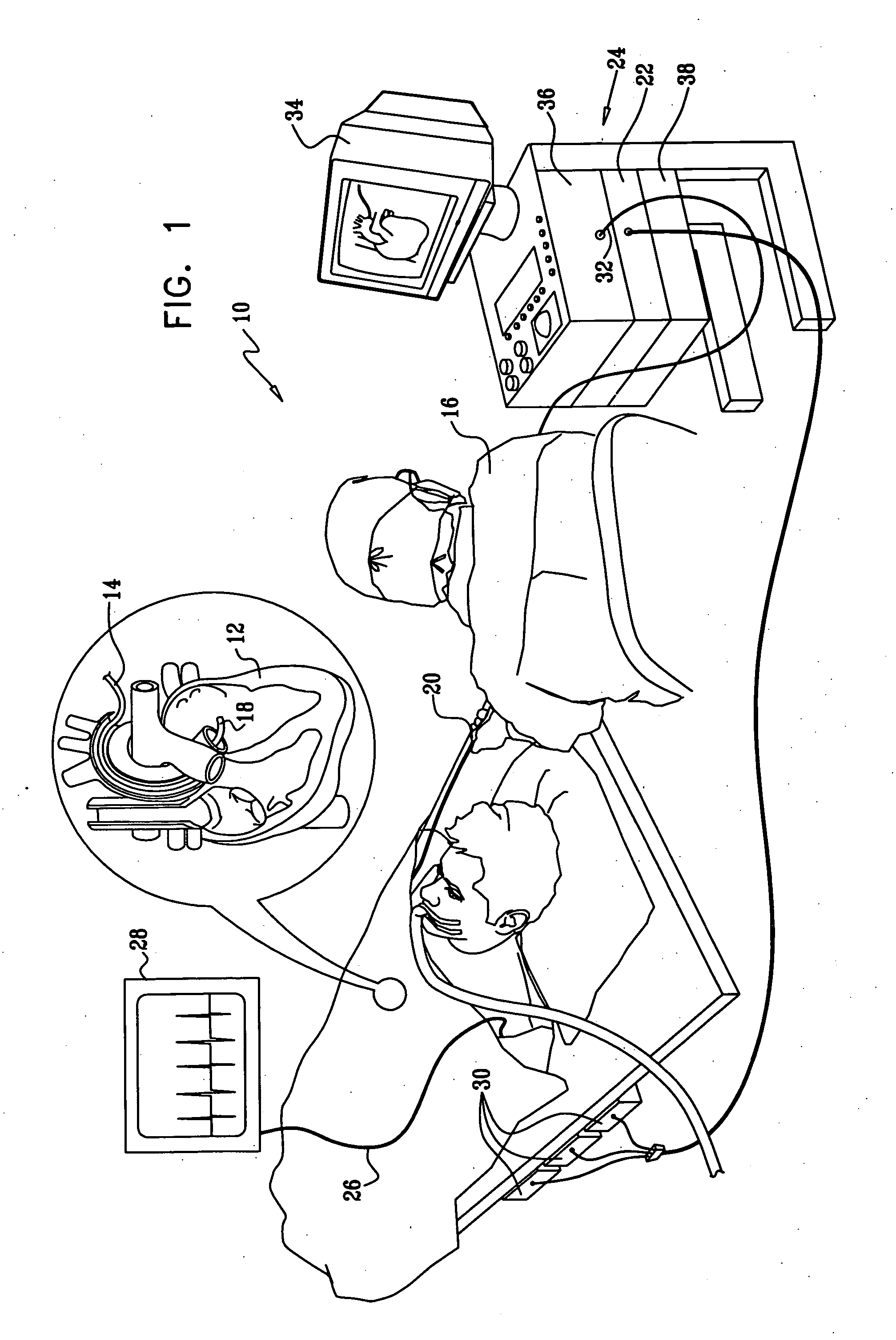
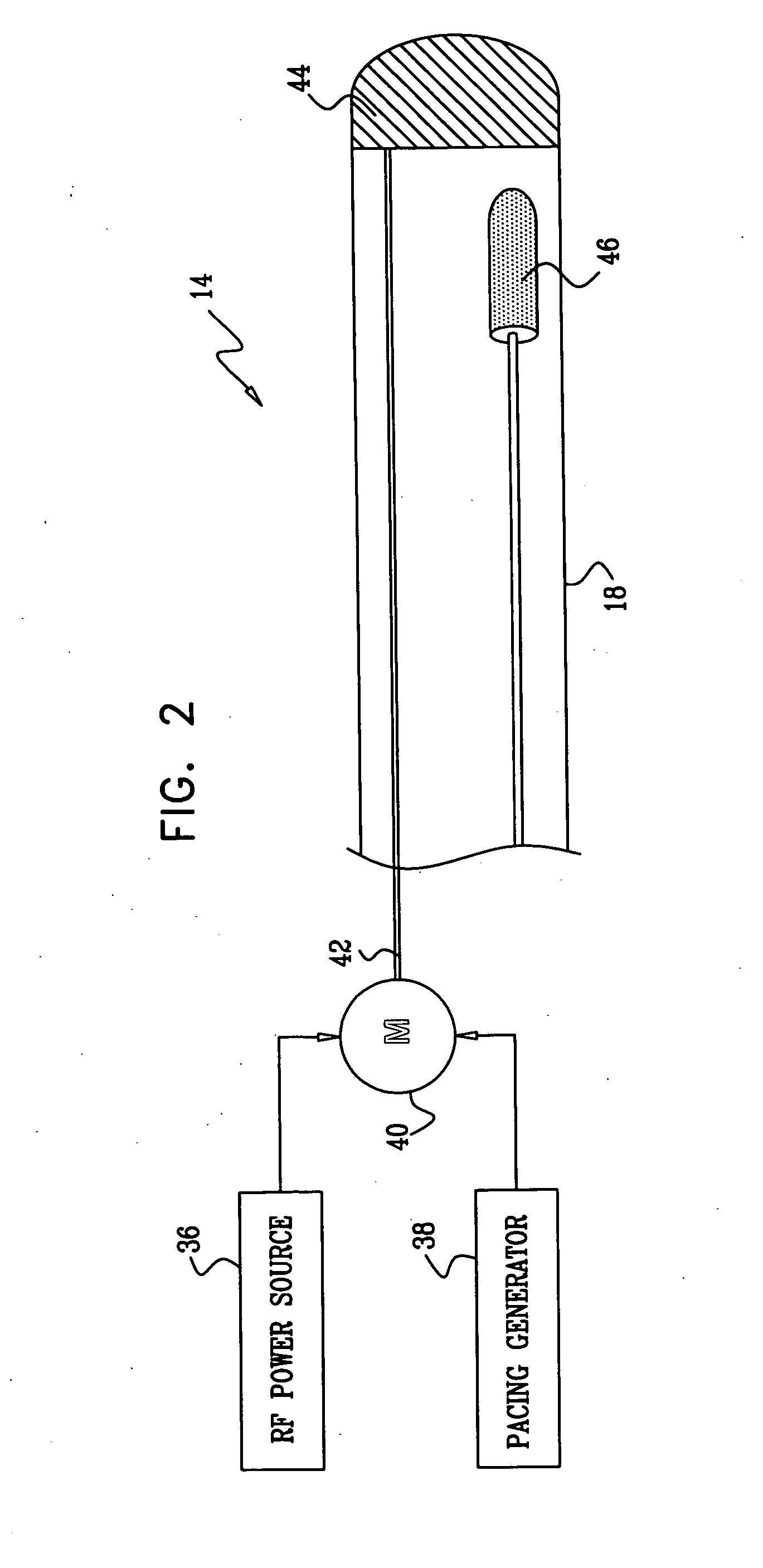
[0035] Turning now to the drawings, reference is initially made to FIG. 1, which is a pictorial illustration of a system 10 for performing ablative procedures on a heart 12 of a living subject in accordance with a disclosed embodiment of the invention. The system comprises a probe, typically a catheter 14, which is percutaneously inserted by an operator 16, who is typically a physician, through the patient's vascular system into a chamber or vascular structure of the heart. The operator 16 brings the catheter's distal tip 18 into contact with the heart wall at a target site that is to be ablated. Radiofrequency electrical current is then conducted through wires in the catheter to one or more electrodes at the distal tip 18, which apply the radiofrequency energy to the myocardium. The energy is absorbed in the tissue, heating it to a point (typically about 50° C.) at which it permanently loses its electrical excitability. When successful, this procedure creates non-conducting lesions...

embodiment 2

[0061] The method disclosed above with reference to FIG. 2 may be combined with other lesion assessment techniques. Reference is now made to FIG. 4, which is a schematic of the distal tip 18 of the catheter 14 (FIG. 1) in accordance with an alternate embodiment of the invention. The distal tip 18, shown in juxtaposition to target tissue 74, is now provided with an array of ultrasound transducers 76 and a temperature sensor 78, for additional lesion production and assessment as described, for example, in U.S. Pat. Nos., 5,443,489, 6,321,109, 6,083,170, 6,301,496 and U.S. Patent Application Publication Nos. 2004 / 0143258 and 2004 / 0147920, whose disclosures are herein incorporated by reference. The transducers 76 and the temperature sensor 78 are connected to suitable signal processing circuitry in the console 24 (FIG. 1), which can be realized as the above-noted Carto-Biosense Navigation System. Lesion assessment may be conducted simultaneously using feedback from electrical obtained u...

embodiment 3

[0069] Reference is now made to FIG. 5, which is an end view of a distal portion 90 of a catheter suitable for use in the system 10 (FIG. 1), in accordance with an alternate embodiment of the invention. In this embodiment, the tip is provided with an ablation electrode 92 having a central aperture 94 measuring about 1-1.5 mm in diameter.

[0070] Reference is now made to FIG. 6, which is a sectional view taken along line 6-6 of the distal portion 90 of the catheter shown in FIG. 5. The electrode 92 extends a short distance behind the tip of the catheter, being delimited by a broken line 96. An ultrasound transducer 98 is positioned a short distance behind the aperture 94, being separated from the distal end of the catheter by a plug 100 of a sonolucent material such as silicon, and having an interface 102 with the plug 100. The transducer 98 is forward looking, and has a field of view 104, indicated by broken lines, with an operational range of about 8 mm. The field of view 104 extend...


PUM


Abstract

Monitoring intracardiac ablation progress in near real time is accomplished by evaluating capture of a pacing signal while ablation energy is concurrently directed to a target site. Sufficiency of ablation is indicated by failure of signal capture at a maximum predetermined pacing voltage. A common electrode in a cardiac catheter is simultaneously used to test pacing capture and to deliver ablation energy.

Description

BACKGROUND OF THE INVENTION [0001] 1. Field of the Invention [0002] This invention relates to methods and systems for the treatment of conduction disturbances of the heart. More particularly, this invention relates to validating and monitoring percutaneous cardiac ablation procedures. [0003] 2. Description of the Related Art [0004] Atrial fibrillation is a well-known disorder of the heart, which causes hemodynamic efficiency to be reduced and which, in serious cases, can lead to cardiac embolization, stroke, ventricular arrhythmias and other potentially fatal complications. Atrial fibrillation is frequently engendered by abnormal electrical conduction paths within the heart muscle. Normally, electrical activation signals are conducted in an orderly way through the atrium and into the ventricle, passing each point in the heart only once in each heart cycle. Electrical activation signals at different locations in the heart are well correlated, taking into account normal propagation de...

Claims


Application Information

Patent Timeline
Patent Type & Authority Applications(United States)
IPC IPC(8): A61B18/18
CPCA61B18/1492A61B19/5244A61B2019/5278A61B2019/5251A61B2019/5276A61B2017/00084A61B2090/3782A61B34/20A61B2034/2051A61B2090/378A61B17/3205A61B17/32
Inventor GOVARI, ASSAFALTMANN, ANDRES CLAUDIOEPHRATH, YARON
Owner BIOSENSE WEBSTER INC
Why Eureka
Try Eureka