
Hybrid oxy-fuel combustion power process

Inactive Publication Date: 2007-08-30
CLEAN ENERGY SYST
View PDF23 Cites 32 Cited by
  • Summary
  • Abstract
  • Description
  • Claims
  • Application Information

AI Technical Summary

Benefits of technology

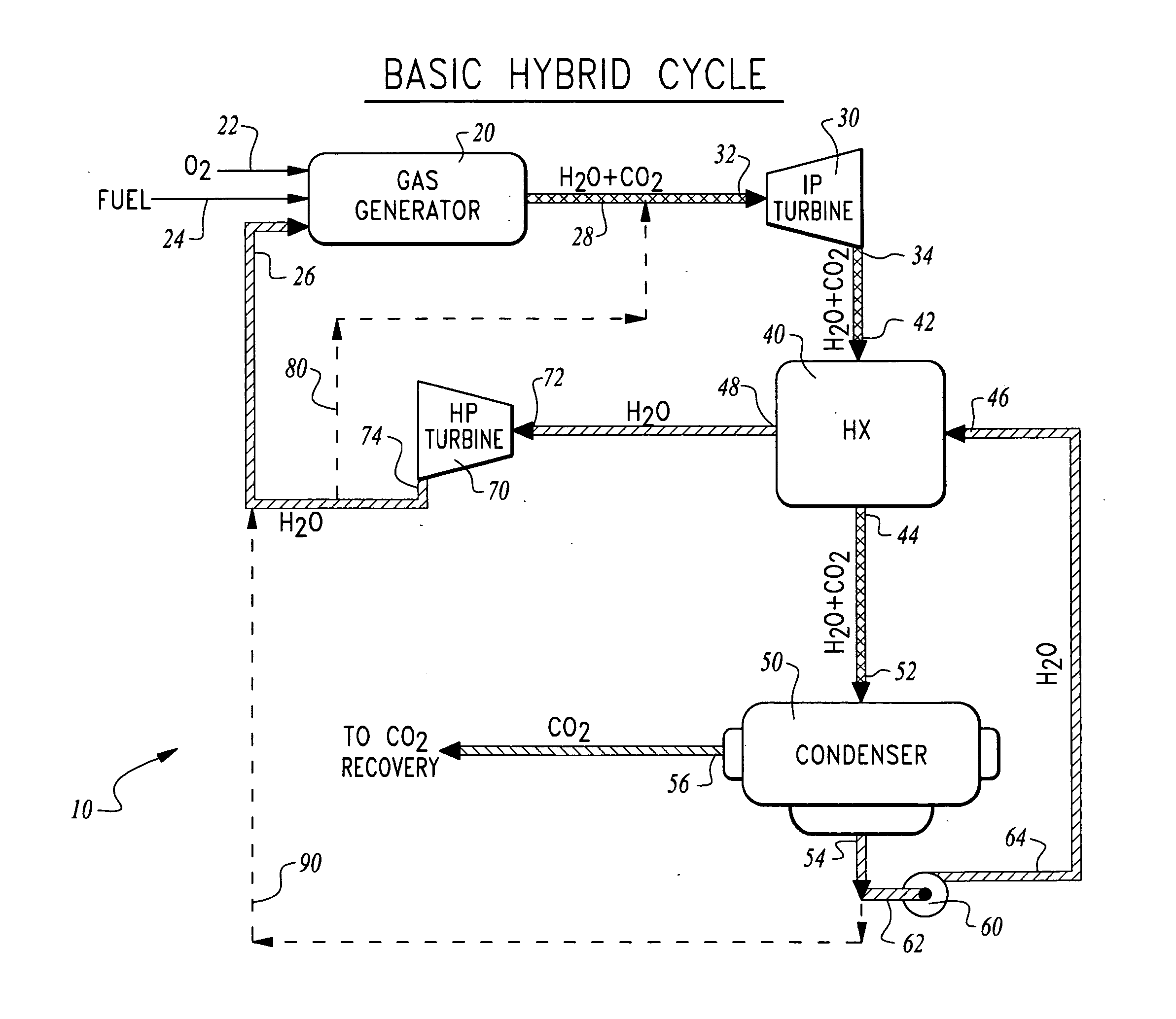
[0010] With this invention a power generation system is provided which utilizes oxy-fuel combustion within a hybrid cycle that combines both gas turbines and steam turbines within a common cycle to maximize the beneficial attributes of both gas turbines and steam turbines while also providing the potential for zero emissions inherent in oxy-fuel combustion power generation systems.
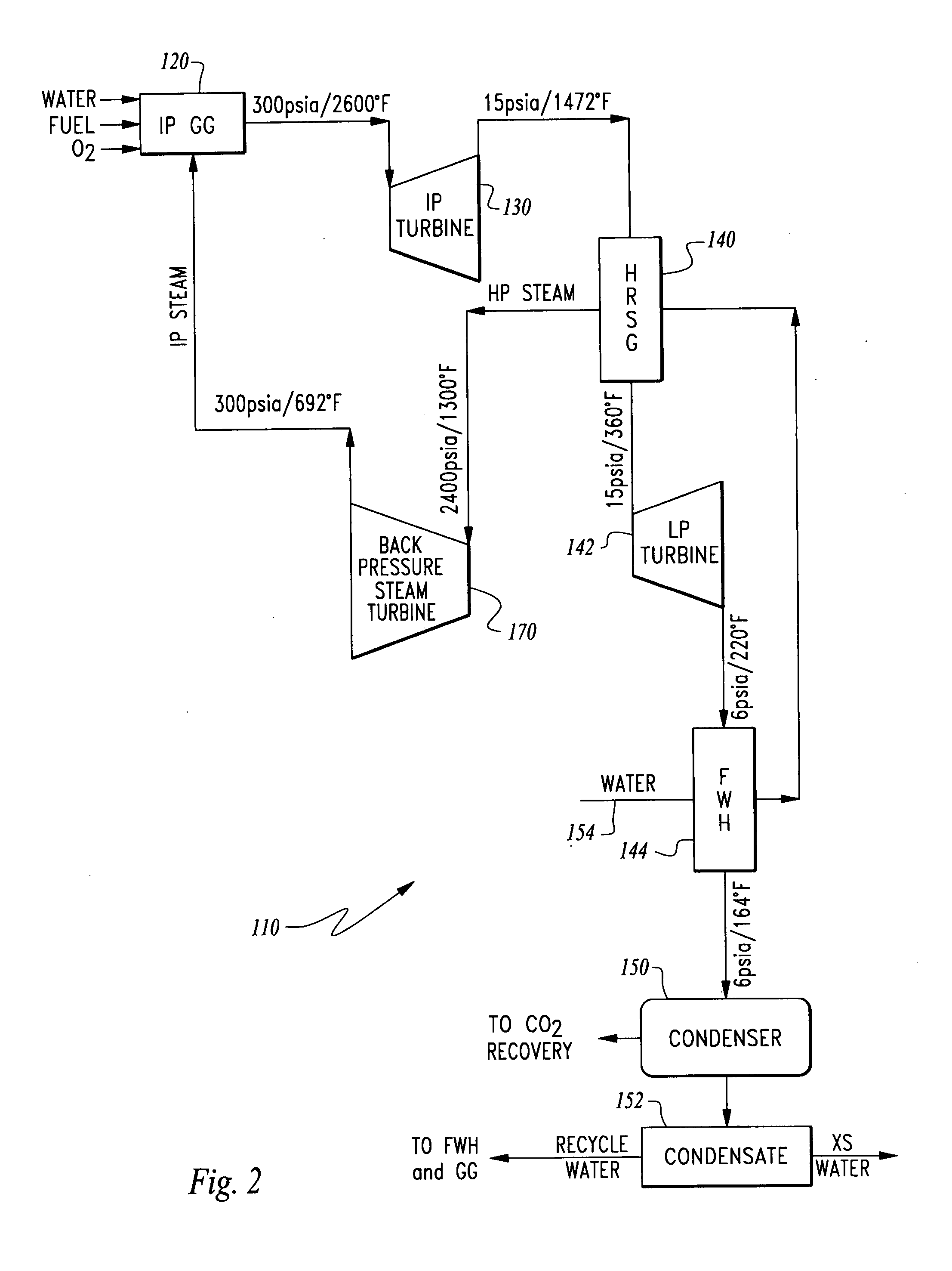
[0012] The drive gas mixture is then passed through a heat exchanger where the drive gas mixture is cooled. The drive gas mixture can optionally be routed through a low pressure drive gas turbine to extract further power from the drive gas mixture. The drive gas mixture can thereafter optionally be routed through a feedwater heater where further cooling of the drive gas mixture takes place. This drive gas mixture would then typically be routed to a condenser or other separator where the drive gas mixture is cooled to the point where the water within the drive gas mixture condenses into a liquid, and carbon dioxide within the drive gas mixture remains a gas. The water is then easily separated and preferably at least a portion of this water is further utilized within the hybrid cycle while excess water can be removed from the system.
[0016] Accordingly, a primary object of the present invention is to provide a power generation system which combusts a hydrocarbon fuel and provides low or zero atmospheric emissions.
[0017] Another object of the present invention is to provide a power generation system which has low or zero emissions and relatively high thermal efficiency for low cost operation.

Problems solved by technology

While such oxy-fuel combustion power generation systems are known to take on a variety of different configurations, a basic arrangement consistent with most embodiments of prior art oxy-fuel combustion power generation systems is limited to turbines or other expanders driven by the drive gas mixture of steam and carbon dioxide.
However, known prior art oxy-fuel combustion power generation systems have not included any turbines or other expanders on this substantially pure water / steam return line passing from the condenser to the gas generator.
However, maximum performance steam turbines have a relatively only moderately high inlet temperature of 1,000° F. to 1,300° F. Similarly, gas turbines have been developed with only moderately high pressures of perhaps up to 1,000 psia.
Because gas generators in oxy-fuel combustion power generation systems produce an exceptionally high temperature and pressure drive gas mixture (up to 3,000° F. or higher and up to 1,500 psia and higher) due to the utilization of substantially pure oxygen as the oxidizer of the hydrocarbon fuel, the prior art steam and gas turbines do not take full advantage of the high temperature (and pressure) oxy-fuel combustion drive gas.
Such a high temperature high pressure drive gas working fluid comprised of a mixture of steam and carbon dioxide is not suited to the inlet conditions and drive gas characteristics of prior art turbines.

Method used


Image

  • Hybrid oxy-fuel combustion power process
  • Hybrid oxy-fuel combustion power process
  • Hybrid oxy-fuel combustion power process

Examples


Embodiment Construction

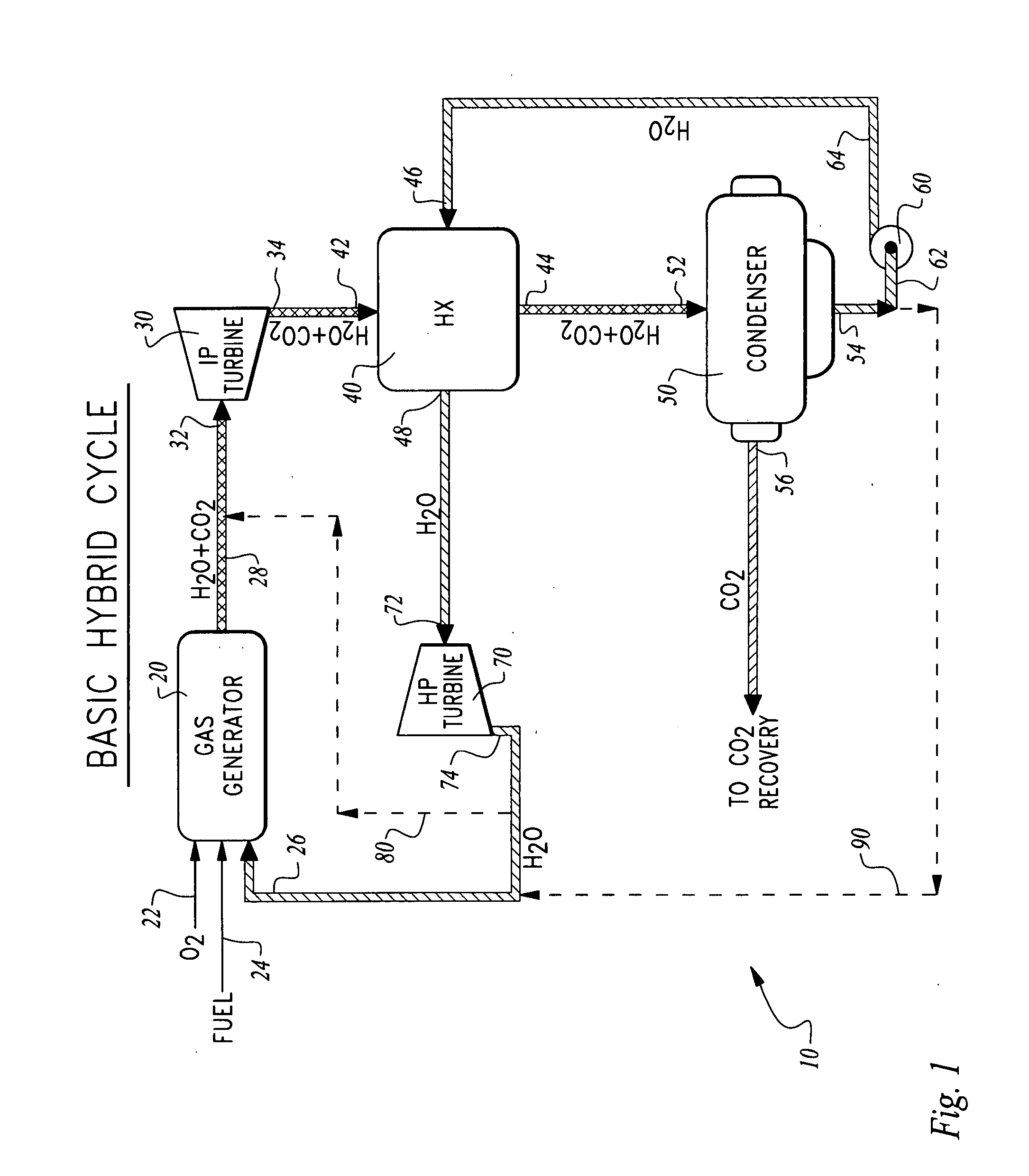
[0024] Referring to the drawings, wherein like reference numerals represent like parts throughout the various drawing figures, reference numeral 10 is directed to a hybrid cycle (FIG. 1) oxy-fuel combustion power generation system according to a most basic exemplary embodiment. With this hybrid cycle 10, two separate working fluids are included within a single cycle with the first of the working fluids being a drive gas mixture of steam and carbon dioxide and a second substantially pure water / steam working fluid.

[0025] Each of the drive gases drives a separate turbine 30, 70. In this way, the hybrid cycle is neither a purely direct cycle with all of the turbines or other expanders driven by exhaust from the gas generator 20 directly, nor is it an indirect cycle in that all of the turbines are driven by a drive gas heated through heat exchangers from the exhaust of the gas generator 20. Rather, one of the turbines is directly driven by the exhaust from the gas generator 20 while the...


PUM


Abstract

A closed loop oxy-fuel combustion power generation cycle is disclosed. The closed cycle has a gas generator which combusts oxygen with a hydrocarbon fuel to produce a drive gas mixture of steam and carbon dioxide that drives a turbine directly with the drive gas mixture. The drive gas mixture then enters a condenser where carbon dioxide is removed and water is recirculated to a heat exchanger where heat is transferred from the drive gas mixture to the water, to produce high pressure steam. This high pressure steam acts as a separate drive gas for a steam turbine. This steam is only indirectly heated by the gas generator through the heat exchanger, such that the cycle includes both direct and indirect heating of working fluids. Water / steam downstream from the steam turbine is then routed back to the gas generator or downstream of the gas generator to close the cycle.

Description

CROSS-REFERENCE TO RELATED APPLICATIONS [0001] This application claims benefit under Title 35, United States Code §119(e) of U.S. Provisional Application No. 60 / 775,491 filed on Feb. 21, 2006. STATEMENT REGARDING FEDERALLY SPONSORED RESEARCH OR DEVELOPMENT [0002] This invention was made with Government support under Collaborative Research Agreement No. DE-FC26-05NT42465 awarded by the Department of Energy. The Government has certain rights in this invention. FIELD OF THE INVENTION [0003] The following invention relates to processes and systems for power generation through combustion of a hydrocarbon fuel with oxygen, such that emissions are reduced or eliminated. More particularly, this invention relates to oxy-fuel combustion power generation systems which have at least two separate expanders with each of the two expanders driven by a unique drive gas, one of the drive gases being substantially pure steam and the other drive gas being a mixture of steam and carbon dioxide. BACKGROU...

Claims


Application Information

Patent Timeline
IPC IPC(8): F02C3/30
CPCF01K17/025F02C1/10F05D2260/61F02C3/34F02C3/30Y02E20/34
Inventor MACADAM, SCOTTHOFFMAN, LAWRENCE C.VITERI, FERMIN
Owner CLEAN ENERGY SYST
Learn More