Method of laser welding, manufacturing method of control unit, and car electronic control unit

a manufacturing method and control unit technology, applied in the direction of printed circuit aspects, manufacturing tools, metal working devices, etc., can solve the problems of reducing product quality, generating problems, and unable to obtain the necessary weld strength, and achieve stable weld quality and low cost.

Inactive Publication Date: 2007-08-30
HITACHI LTD
View PDF8 Cites 34 Cited by
  • Summary
  • Abstract
  • Description
  • Claims
  • Application Information

AI Technical Summary

Benefits of technology

[0016]In accordance with the present invention, it is possible to achieve a stable weld quality at a low cost up to a certain degree of terminal thickness regardless of an outer appearance state of the weld terminal and metal plate.
[0017]Other objects, features and advantages of the invention will become apparent from the following description of the embodiments of the invention taken in conjunction with

Problems solved by technology

As a result, it is hard to obtain a necessary weld strength.
Further, with regard to a laser welding between the terminal mentioned above and the bus bar, they are not welded if they are not in contact with each other, and there is a possibility that a product quality is lowered.
However, even in this case, if an individual difference is great in a reflection coefficient of the laser beam in correspondence to an outer appearance surface state of the weld terminal, the same problem may be generated.
In the case of the plastic molding modularized unit, the terminal surface is exposed to a high temperature at a time of being filled with the resin, and it is hard to fix its color.
In the case that it is impossible to homogenously align a surface state through a production period of the product, there is considered that a quality dispersion caused by the welding under a fixed condition becomes large and a extraction rate is deteriorated.
In order to deal with the problem mentioned above, there can be considered to execute the welding while adjusting one position to one position by a manual procedure, however, in the case that

Method used


Image

  • Method of laser welding, manufacturing method of control unit, and car electronic control unit
  • Method of laser welding, manufacturing method of control unit, and car electronic control unit
  • Method of laser welding, manufacturing method of control unit, and car electronic control unit

Examples


embodiment 1

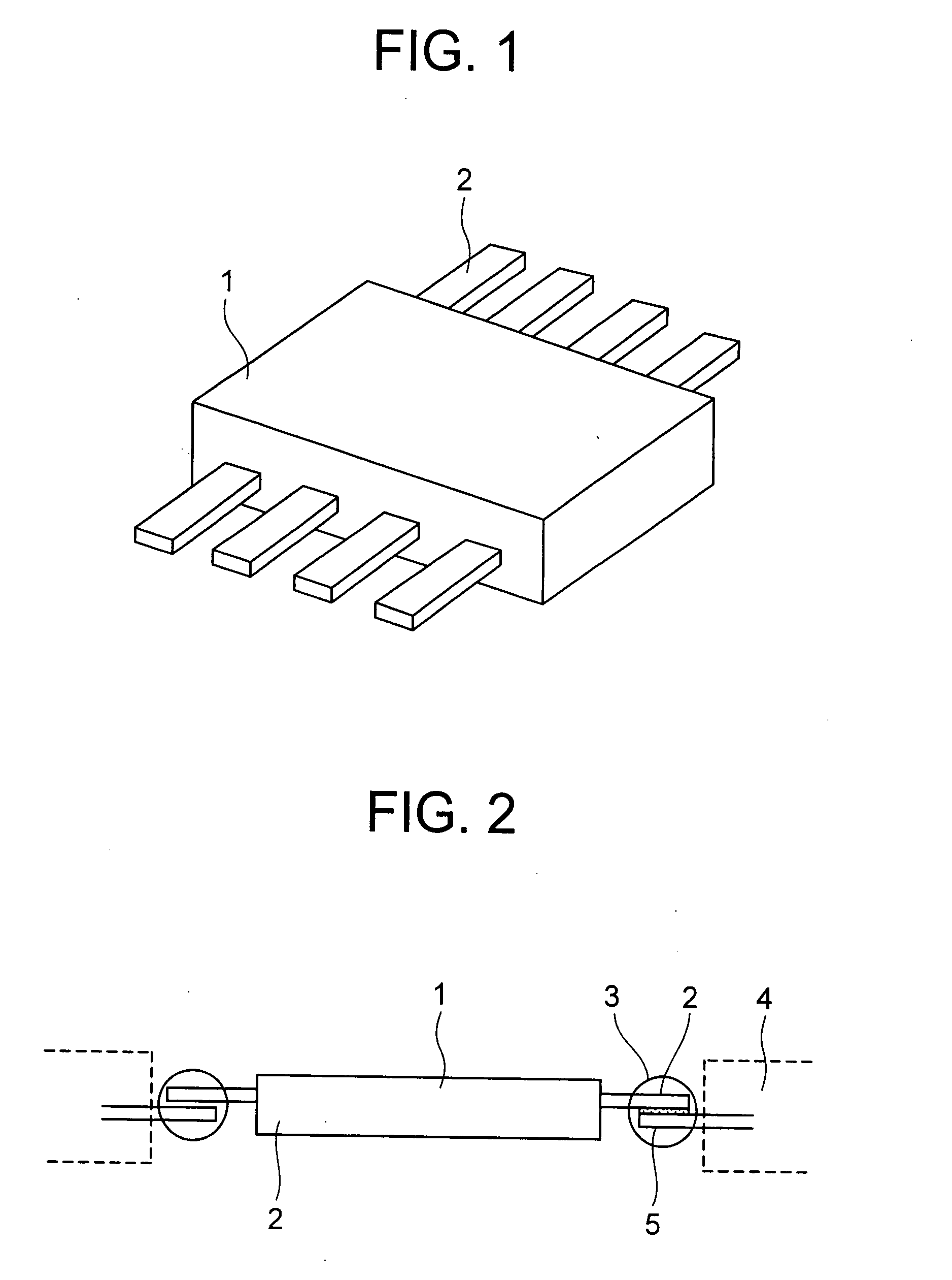
[0041]FIG. 1 is a schematic view of a resin-sealed integrated circuit apparatus to which a laser welding in accordance with the present invention is applied.

[0042]The integrated circuit apparatus is constituted by having a main body portion 1 structured by sealing an integrated circuit by resin, a terminal 2 provided in such a manner as to protrude from the main body portion 1 sealed by a plastic molding for inputting and outputting a signal to and from the integrated circuit and supplying an electric power. Each of the terminals 2 is provided with a hole for welding to a bus bar. The integrated circuit apparatus is specifically achieved, for example, as a power module controlling a drive power to a motor for controlling a drive of the motor serving as an actuator for actuating a caliper, in an electro mechanical brake apparatus.

[0043]FIG. 2 is a schematic view showing an assembled state of the integrated circuit apparatus to a resin casing.

[0044]A resin casing 4 is constituted, for...

embodiment 2

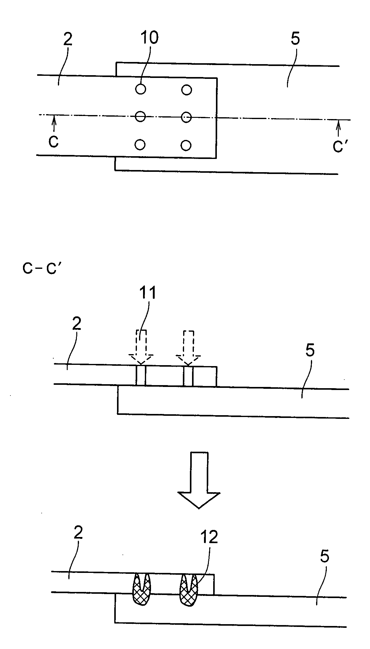
[0052]FIG. 6 is a top elevational view and a cross sectional view of a welding operation portion in accordance with a second embodiment.

[0053]In the present embodiment, since the hole 10 has the shape characteristic, it is possible to position on the basis of the image recognition. A weld position 12 melting around the hole 10 reaches the bus bar 5 by irradiating a laser welding arc 11 to the hole 10 recognized on the basis of the image recognition, whereby a bonding to the terminal 2 is achieved. Since the diameter of the laser welding arc 11 irradiated at this time is larger than the hole 10, it is possible to weld one hole 10 by one irradiation. In other words, in the case that the hole 10 is provided at six positions, as illustrated, six times of laser irradiations are executed.

embodiment 3

[0054]FIG. 7 is a top elevational view and a cross sectional view of a welding operation portion in accordance with a third embodiment of the present invention.

[0055]In the present embodiment, a hole 13 provided in the terminal 2 is provided with a projection portion toward an inner side thereof. The special shaped hole 13 is provided in a welding operation portion lapping over the bus bar 5 in the terminal 2. As shown in the top elevational view in FIG. 7, since the special shaped hole 13 has a shape characteristic, it is possible to position on the basis of the image recognition. A weld position 14 formed by melting a projection of the special shaped hole 13 reaches the bus bar 5 so as to be bonded to the terminal 2, by irradiating the laser welding arc to the special shaped hole 13 recognized on the basis of the image recognition. At this time, the number and the layout of the projections directed to the inner side of the hole can be optionally set.

[0056]In the embodiments descri...


PUM

PropertyMeasurementUnit
Timeaaaaaaaaaa
Forceaaaaaaaaaa
Diameteraaaaaaaaaa

Abstract

The invention stabilizes a quality of a laser welding in a terminal in which an outer appearance characteristic is not stabilized, and achieves an improvement of a positioning characteristic at a time of executing the laser welding without generating a cost increase. A hole is formed in a terminal of an integrated circuit sealed by a plastic molding. At a time of welding, a welding operation position is positioned by recognizing the hole in accordance with an image recognition, and a laser welding is executed by irradiating a laser beam to a portion of a terminal and a bus bar positioned near an edge portion of the hole. The hole is preferably formed in a circular shape or a similar shape thereto.

Description

BACKGROUND OF THE INVENTION[0001]1. Field of the Invention[0002]The present invention relates to a car electronic control unit, a manufacturing method of the same and a terminal welding method.[0003]2. Description of Related Art[0004]As a brake apparatus of a motor vehicle, there has been developed an electro mechanical brake apparatus which electrically detects a pedaling pressure of a brake pedal and electromechanically generates a brake force corresponding to the detected pedaling pressure. In the electro mechanical brake apparatus, it is possible to individually control the brake force of each of wheels. Further, there has been considered that a control unit for executing a brake force control is provided in each of the wheels for the control mentioned above. For drive controlling a motor corresponding to an actuator actuating the control unit mentioned above, for example, a caliper, the apparatus is filled with resin so as to be modularized, and a terminal thereof is connected ...

Claims


Application Information

Patent Timeline
IPC IPC(8): B23K26/22B23K26/02B23K26/21H01R4/02H01R43/02
CPCB23K26/246B23K2201/42H01R43/0221H05K3/202H05K2203/107H05K2201/10689H05K2201/10818H05K2201/1084H05K3/328B23K26/244B23K2101/42
Inventor WATANABE, HIROFUMIYASUKAWA, DAISUKESUZUKU, MASAAKI
Owner HITACHI LTD
Why Eureka
Try Eureka