RFID tag and ceramic patch antenna

a technology of ceramic patch antenna and rfid tag, which is applied in the direction of burglar alarm mechanical actuation, instruments, packaged goods types, etc., can solve the problems of inability to adapt, thin, flat, and adaptable conventional rfid tags incorporating coils, and achieve the effect of wide application rang

Inactive Publication Date: 2007-08-30
SONTEC
View PDF3 Cites 42 Cited by
  • Summary
  • Abstract
  • Description
  • Claims
  • Application Information

AI Technical Summary

Benefits of technology

[0008]RFID tags Recently, and related systems have a wide range of application. For example, they can be used in automated gate access control applications to protect security areas from unauthorized access. In such cases, tags are often manufactured in the form of access control card. The information embedded in the RFID tags enables identification and authentication of persons who approach the secured area. The legacy gate control applications require persons who access building to provide authentication information from their identification tags to the reader, whether by inserting or typing. New RFID tag systems have eliminated the necessity of manually entering authentication data by providing such data through automated wireless transmission technology. More specifically, a user simply holds or locates RFID tags near the base station which is in connection with the security system. The base station transmits exciter signal to power up and activate the RFID tag circuit, so that the tag circuit can send back its information which is received and decoded by the base station to determine authentication. In addition, RFID tags can be written with properly excited and modulated signals remotely.

Problems solved by technology

The major problem in the bar code system is that bar code printing has to be properly aligned with the reader.
One another important problem is that printed bar code can be damaged to be unreadable by exposure to moisture or abrasion.
Conventional RFID tags which incorporate coils are subject to limitation in their being thin, flat, and adaptable, not mentioning relevant cost.
Especially, printing near the coil antenna is restricted.

Method used


Image

  • RFID tag and ceramic patch antenna
  • RFID tag and ceramic patch antenna
  • RFID tag and ceramic patch antenna

Examples


Embodiment Construction

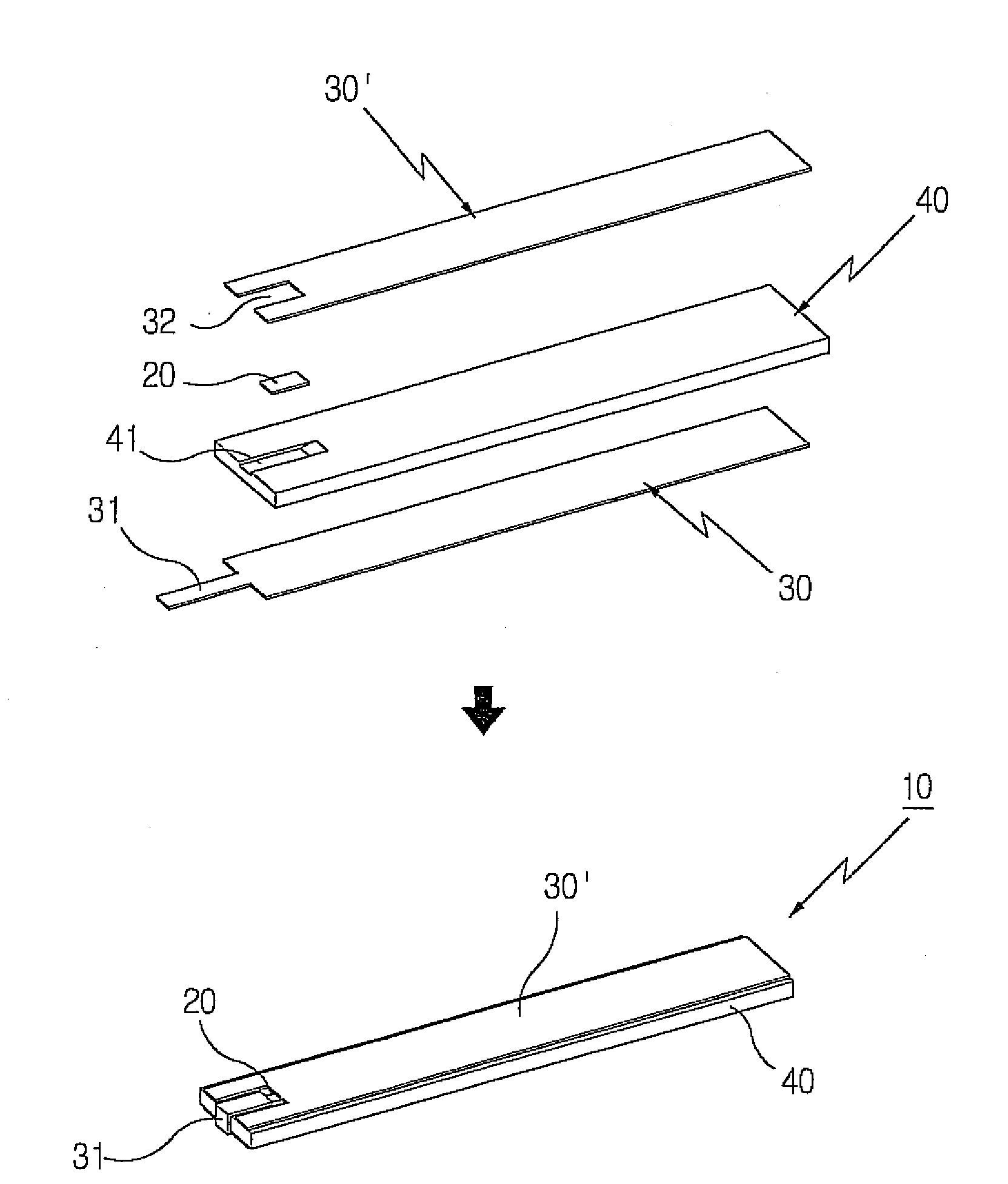
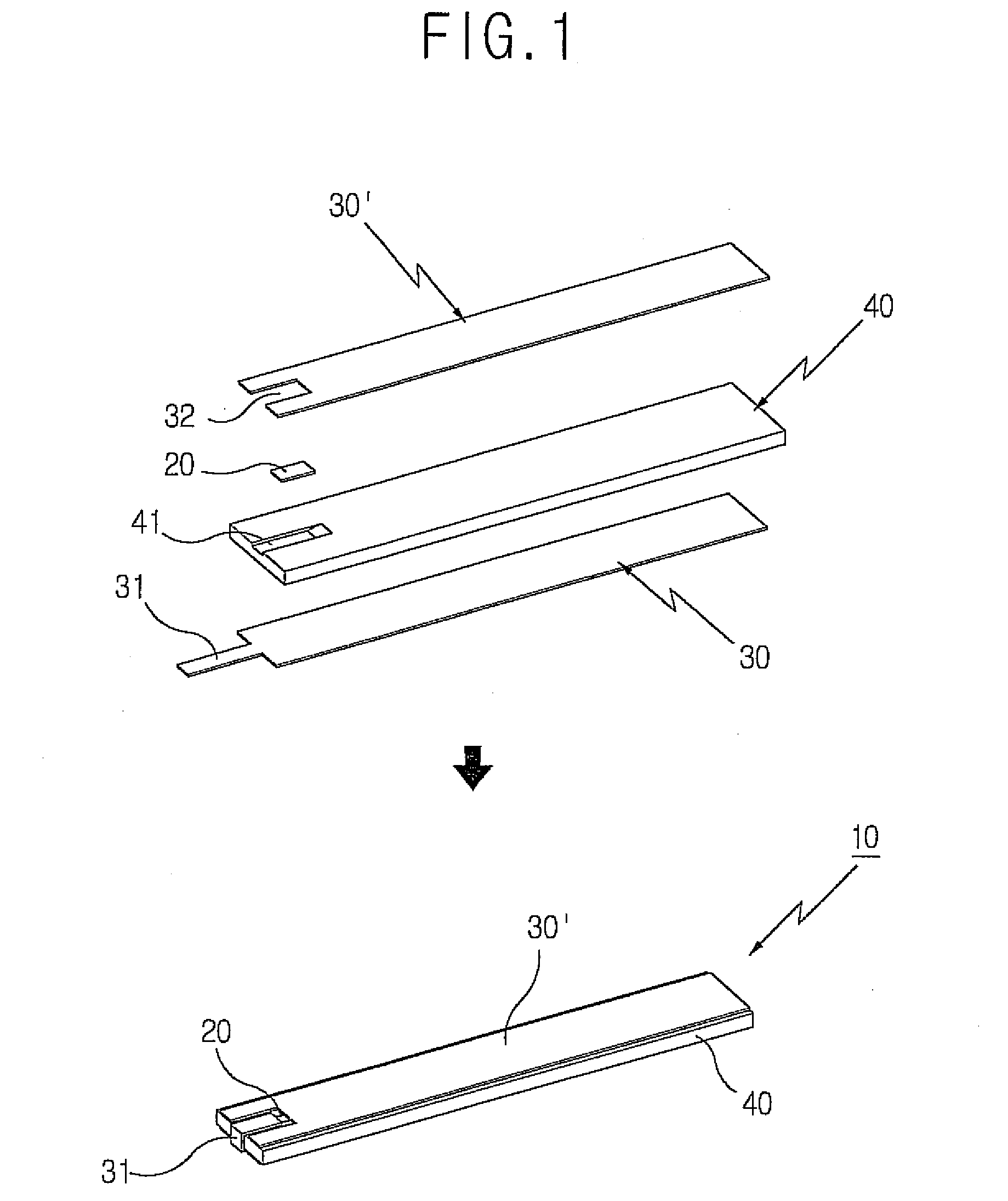
[0028]The present invention relates to a design and method which can solve abovementioned problems. This invention is aiming at manufacturing antennas with very thin metal plate, in their diverse shapes and configurations, enabling acceptable receiving rate, manufacturing cost reduction, and simple process.

[0029]According to this invention, the antennas connecting both ends of the RFID chips can be formed by painting, spraying, or printing with conductive ink, enabling easy forming in diverse shapes, very thin, reducing manufacturing facilities and relevant cost, while maintaining their performance.

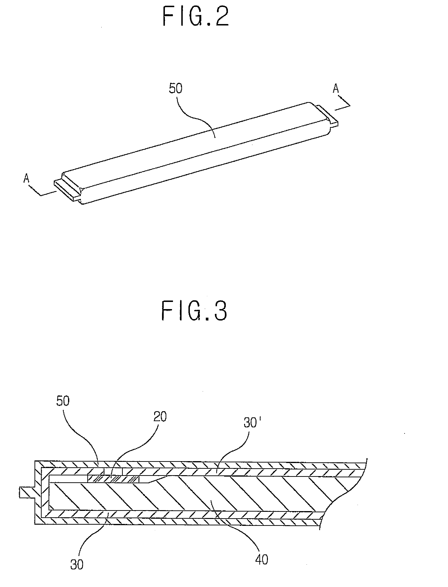
[0030]Furthermore, by forming dielectric member using ceramic substance of which permittivity is 4.0˜210, dimensions of the dielectrics can be significantly downsized, enabling compact and light antenna. Therefore, RFID chips produced in accordance with this invention can be affixed to moving or small objects. The ceramic patch antennas produced in accordance with this invention have high...


PUM


Abstract

This invention relates to a radio frequency identification (RFID) tag and ceramic patch antenna for radio frequency identification systems. The radio frequency identification tag in accordance with this invention comprises; lower antenna member of which one end is formed with coupling projection for conjoining; upper antenna member of which one end is formed with coupling groove for conjoining; an RFID chip of which one end is conjoined with the coupling projection of the said lower antenna member and the other end is conjoined with the coupling groove of the said upper antenna member, containing the information of the objective management item which communicates with the terminal device; and a spacer which electrically isolates the said antenna members. The said antenna members are conjoined on the top and bottom sides of the said spacer in parallel direction. The RFID chip which is conjoined with the said antenna members is placed on the top or bottom side of the said spacer.
The ceramic patch antenna in accordance with this invention comprises; a dielectric ceramic member formed with ceramic substance of which the permittivity is 4.0˜210 and formed with a feeder hole punched at the center; conductive film formed on one side of the said dielectric ceramic member; an earth plate affixed on the other side of the said dielectric ceramic and formed with a punched feeder hole at the center; a feeder pin which is inserted in the feeder hole of the said dielectric ceramic and contacted with and feeds electricity to the said conductive film. The said feeder pin is inserted into the feeder hole of the said dielectric ceramic. The said conductive film covers the feeder hole formed in the said dielectric ceramic and electrically contacts with the feeder pin inserted into the feeder hole, The feeder hole of the said earth plate is formed larger than the feeder hole of the said dielectric ceramic, so that electrically isolated with the said feeder pin.

Description

CROSS-REFERENCE TO RELATED APPLICATIONS[0001]Pursuant to 35 U.S.C. §119(a), this application claims the benefit of U.S. Provisional Application Ser. No. 10-2006-0019547 filed on Feb. 28, 2006, the contents of which is hereby incorporated by reference herein in its entirety.BACKGROUND OF THE INVENTION[0002]1. Field of the Invention[0003]This invention relates to a RFID Tag and Ceramic Patch Antenna. More specifically, this invention relates to the RFID tags which can be manufactured with easily formable antenna at acceptable cost, while maintaining successful receiving rate, by forming the antenna conjoining at both ends of the RFID chip by printing, spraying, or painting with conductive ink.[0004]Furthermore, by forming dielectric members using ceramic substances of which permittivity is 4.0˜210, the size of the dielectric members can be greatly reduced which results in compact and light antenna members so that they can be affixed to moving bodies or small objects. The ceramic patch...

Claims


Application Information

Patent Timeline
Patent Type & Authority Applications(United States)
IPC IPC(8): G08B13/14
CPCG06K19/07749H01Q9/0407H01Q1/2225A61G17/08B65D85/50B65D2585/00
Inventor LEE, DONG-JIN
Owner SONTEC
Why Eureka
Try Eureka