
Method and system to enhance energy savings in multicast transmissions in WLAN

a multicast transmission and energy saving technology, applied in the field of multicast transmission service optimization in wlan networks, can solve the problems of multicast packet burst after the dtim interval, and consume energy, so as to improve the ap originating multicast traffic, enhance the multicast performance, and save energy. the effect of greatest

Inactive Publication Date: 2007-08-30
NOKIA CORP
View PDF12 Cites 48 Cited by
  • Summary
  • Abstract
  • Description
  • Claims
  • Application Information

AI Technical Summary

Benefits of technology

[0022] One advantage of the present invention is that it provides a technique to determine how multicast traffic can be transmitted in the WLAN in a way that problems in the prior art described above can be avoided. For example, by using the technique of the present invention the terminal can avoid receiving and processing most unnecessary data packets. The terminal can also stay in the power save mode for a longer time. The present invention focuses to improve AP originating multicast traffic, which is believed to be the most important direction where greatest energy saving can be achieved. Moreover, the present invention enables the terminal originated multicast traffic and AP originated unicast traffic to work as it works in current 802.11 specifications.
[0023] The present invention has applications in IPTV like video distribution over WLAN network, and provides a mechanism for enhancing WLAN multicast performance to take account battery powered mobile terminals. The aim is to improve current multicast performance from an energy saving point of view. For example, the present invention may be used in IPTV like video or audio streaming using scalable IP multicast. Multicast is good for this kind of delivery, because receiving terminals do not have to acknowledge each received packets as they do with unicast packets. This allows receivers to consume much less energy if compared to unicast reception. Energy consumption is critical issue when building IPTV like services for mobile terminals.
[0024] Moreover, although the present invention is described for 802.11 WLAN, the basic idea may be used also in other unidirectional or bi-directional radio transmission networks to deliver scalable IP multicast traffic, taking advantage of the key idea to transmit multicast packets in certain time slots so that the receiver can switch its receiver circuitry on at specific time to receive packets from a certain multicast address. Distribution of IP packets to these slots can be calculated directly from packets IP address. IP address information is all that is needed by receivers to perform optimal energy saving pattern based on their multicast group join status. Because all entities can calculate transmission time independently, there is no need exchange information about transmission times. This allows this distribution mechanism to work also with unidirectional wired or wireless bearer.
[0025] In summary, the key points in the present invention are as follows:
[0026] 1) Multicast address is used to calculate the MTMAP, where the method to do this calculation is known by all entities. This allows this mechanism to work also with unidirectional bearer, and there is no need to send information from the receiving terminal to the AP to subscribe packet sending.
[0027] 2) Multicast packet sending starts only at time points told by MTMAP, which allows terminals to avoid receiving unnecessary packets. Multicast transmission can span over into the next slots where the AP can continue sending in the following slots. In the case when transmission spans over into next slots and there are packets waiting for transmission starting in the next slots, the AP can decide and prioritize the transmission order of the packets belonging to different slots. This sending may also span over the DTIM period limit.

Problems solved by technology

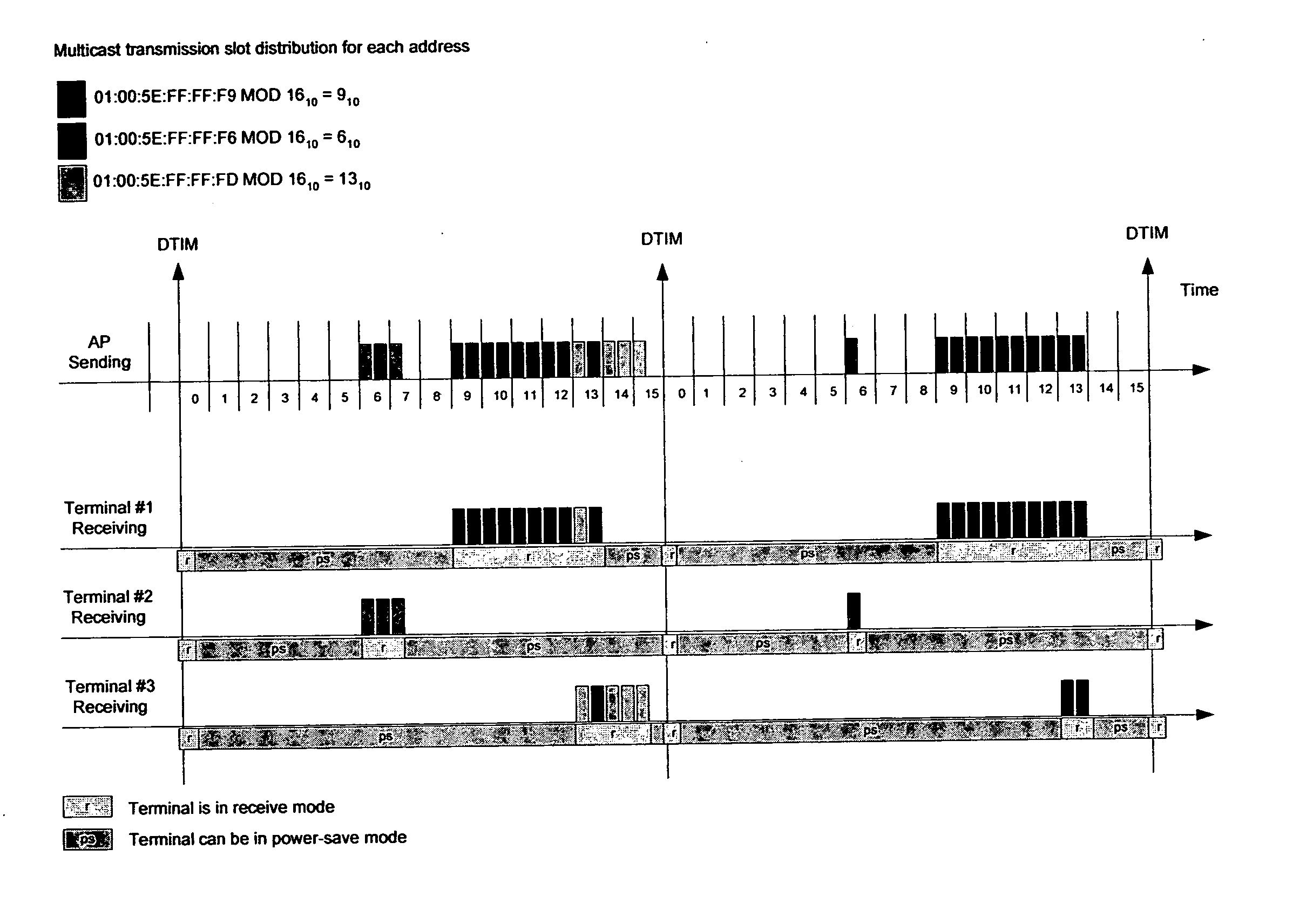
The problem is that the current multicast functionality in the WLAN causes transmission bursts just after deliver traffic indication message (DTIM) intervals.
This causes two problems: First, all stations must be in the receive mode to be able to receive multicast packets.
In addition, receiving and discarding unnecessary multicast packets consumes also energy.
The second problem in the current method is that all multicast packets come in burst after the DTIM interval.
This is not optimal from a radio spectrum usage point of view.
In this example, terminal #2 suffers a lot by this kind of functionality, because it must listen for all multicast packets to get those few packets it is really needs to.

Method used


Image

  • Method and system to enhance energy savings in multicast transmissions in WLAN
  • Method and system to enhance energy savings in multicast transmissions in WLAN
  • Method and system to enhance energy savings in multicast transmissions in WLAN

Examples


Embodiment Construction

[0037] The present invention provides a new and unique method and apparatus for communicating information between two nodes, STAs, points or terminals in a wireless local area network (WLAN), featuring one or more steps for creating an association between multicast transmission scheduling and multicast internet protocol (IP) addresses within a multicast transmission period, and mapping multicast transmission start times using the multicast IP or ethernet address information.

[0038]FIG. 5 shows an example of the enhanced multicast transmission according to the present invention, where the DTIM period is split into a certain amount of time slots, each time slot having associated to it certain multicast addresses. As shown, the DTIM period is split, for example, into 16 time slots labelled 0, 1, 2, . . . , 15. The number of these slots may depend on the DTIM period length. In view of this, the scope of the invention is not intended to be limited to 16 time slots, because embodiments ar...


PUM


Abstract

A new and unique method and apparatus are provided for communicating information between two nodes, points or terminals in a wireless local area network (WLAN) environment or other suitable network environment, featuring one or more steps for creating an association between multicast transmission scheduling and multicast internet protocol (IP) and ethernet addresses within a multicast transmission period, and mapping multicast transmission start times using the multicast IP or ethernet address information. The apparatus may take the form of a wireless local area network (WLAN) or other suitable network having the two nodes or points that communicate information between the same based on the association and mapping, as well as the first or second node, point or terminal in such a wireless local area network (WLAN) environment, or other suitable network environment. The first or second node, point or terminal may include an access point or a station (STA).

Description

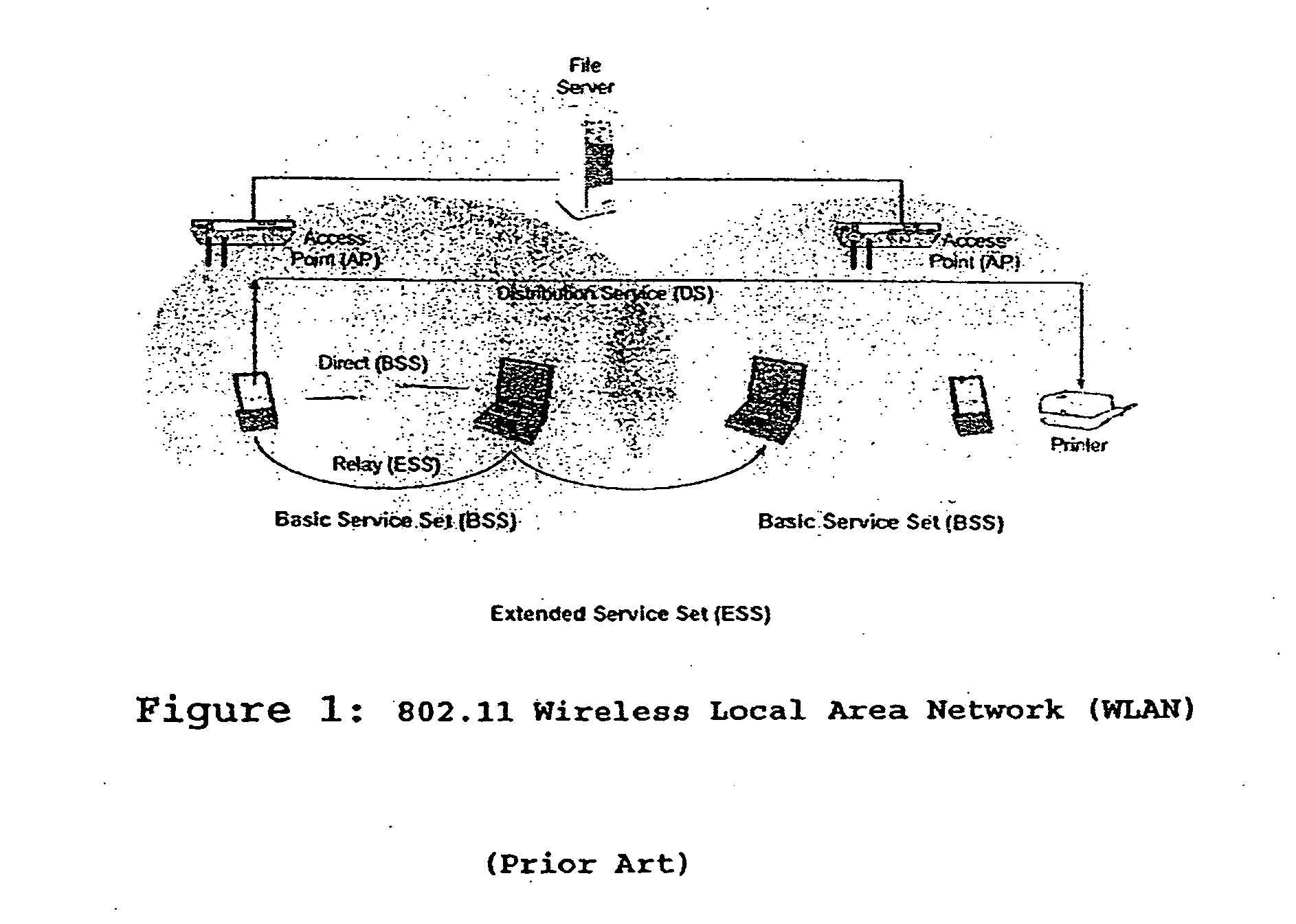
BACKGROUND OF THE INVENTION [0001] 1. Field of Invention [0002] The present invention related to a method and apparatus for providing multicast service optimisations in WLAN networks, including that set forth in IEEE 802.11; and more particularly relates to a method and apparatus for enhancing WLAN multicasting operation especially in view of client terminal power saving. [0003] 2. Description of Related Art [0004]FIG. 1 shows, by way of example, typical parts of an IEEE 802.11 WLAN system, which is known in the art and provides for communications between communications equipment such as mobile and secondary devices including personal digital assistants (PDAs), laptops and printers, etc. The WLAN system may be connected to a wired LAN system that allows wireless devices to access information and files on a file server or multimedia streaming server other suitable device or connecting to the Internet. [0005] The devices can communicate directly with each other in the absence of a bas...

Claims


Application Information

Patent Timeline
IPC IPC(8): H04Q7/24H04L12/56H04W4/06H04W52/02
CPCH04L12/189H04L29/12028H04L45/00Y02B60/50H04L61/103H04W72/005H04W52/0216H04L45/16Y02D30/70H04W72/30
Inventor LAINE, PETRI T.PIIKIVI, LAURI
Owner NOKIA CORP
Learn More