Methods and devices for improving efficiency of wind turbines in low wind speed sites

a wind turbine and low wind speed technology, applied in the direction of electric generator control, machines/engines, mechanical equipment, etc., can solve the problems of unsafe operation at high wind speed, insufficient conventional methods of generating electricity, and insufficient low wind speed operation to meet the ever-growing need for electric power, etc., to achieve optimum aerodynamic efficiency, simple and economical, and controllable performance

Inactive Publication Date: 2007-09-06
APPA KARL +1
View PDF16 Cites 15 Cited by
  • Summary
  • Abstract
  • Description
  • Claims
  • Application Information

AI Technical Summary

Benefits of technology

[0015] In view of such problems of the prior art, the primary object of the invention is to provide a simple and economical wind turbine blade design which effectively achieves easy-starting from a stationary state, optimum aerodynamic efficiency at low and design wind speeds and controlled performance at high wind speeds. A secondary object of the invention is to provide a simple and economical wind turbine blade design which effectively achieves reduced noise production without sacrificing aerodynamic efficiency. The authors are currently developing such a product under funding from the California Energy Commission.
[0016] The invention features a wind turbine blade which has a passive pitching device governed by the centrifugal force of the rotor blade, the resisting force of the axial compression spring and a cam groove which determines the blade angle of incidence. The device ensures the rotor blades are at the optimum angle of incidence in the stationary position. As the rotor turns, the net force between centrifugal force on the blade and the resistant force from the compression spring causes the device to move axially outward while rotating to adjust the pitch of the rotor blade so that angle of incidence is optimal for the given wind speed. As the wind speed exceeds the design speed and the centrifugal force on the rotor blade continues to increase, the device continues the move axially outward while rotating in the opposite direction as to adjust the pitch of the blade in the opposite direction so that the rotor performance is controlled and severe dynamic loads are avoided.
[0017] The invention further features a wind turbine blade which has a forward swept leading edge configuration which deforms in an optimally designed manner to minimize vortex shedding and flow separation at the tip sections to minimize induced drag and improve aerodynamic efficiency. Thus, the blade tip section provides improved lift distribution and consequently increased power extraction capability. Composite materials such as glass and carbon fiber fabrics will be used to tailor the blade design and fabrication to avoid aeroelastic stability problems, which are generally associated with forward swept blade configurations.
[0018] Still another feature of the present invention is the provision of such a system, which minimizes the noise level (dB) due to sweep angle of the blade. The sound pressure is proportional to the fifth power of the tip speed, which is the cosine component of the sweep angle.

Problems solved by technology

In recent years, it has become apparent that conventional methods of generating electricity will soon be insufficient to meet the world's ever-growing need for electric power.
Previously, problems included inefficient operation at low wind speeds and unsafe operation at high wind speeds.
Such active servo-controls are too costly to implement in small wind turbines.
Consequently, there is not enough torque to overcome the generator bearing friction and its magnetic cogging-torque and thus small turbines fail to self-start in low wind speed conditions.
This approach however does not help self-starting in low wind conditions.
The negative effect of this is reduced power generation.
In the case of an aft-swept wing or blade, there is flow separation at the wing tip leading to reduced control effectiveness.
Moreover, strong tip vortex shedding results in high induced drag which opposes the torque and reduces power.
Thus the tip section of an aft-swept blade, although reduces noise, becomes aerodynamically less efficient.
But, this approach again, would not help self-start in low wind speed conditions.
This invention has not yet been reduced to practice and it may be impractical or uneconomical for implementation in low cost small wind turbines.

Method used


Image

  • Methods and devices for improving efficiency of wind turbines in low wind speed sites
  • Methods and devices for improving efficiency of wind turbines in low wind speed sites
  • Methods and devices for improving efficiency of wind turbines in low wind speed sites

Examples


Embodiment Construction

1. Preferred Embodiments of the Invention Drawings

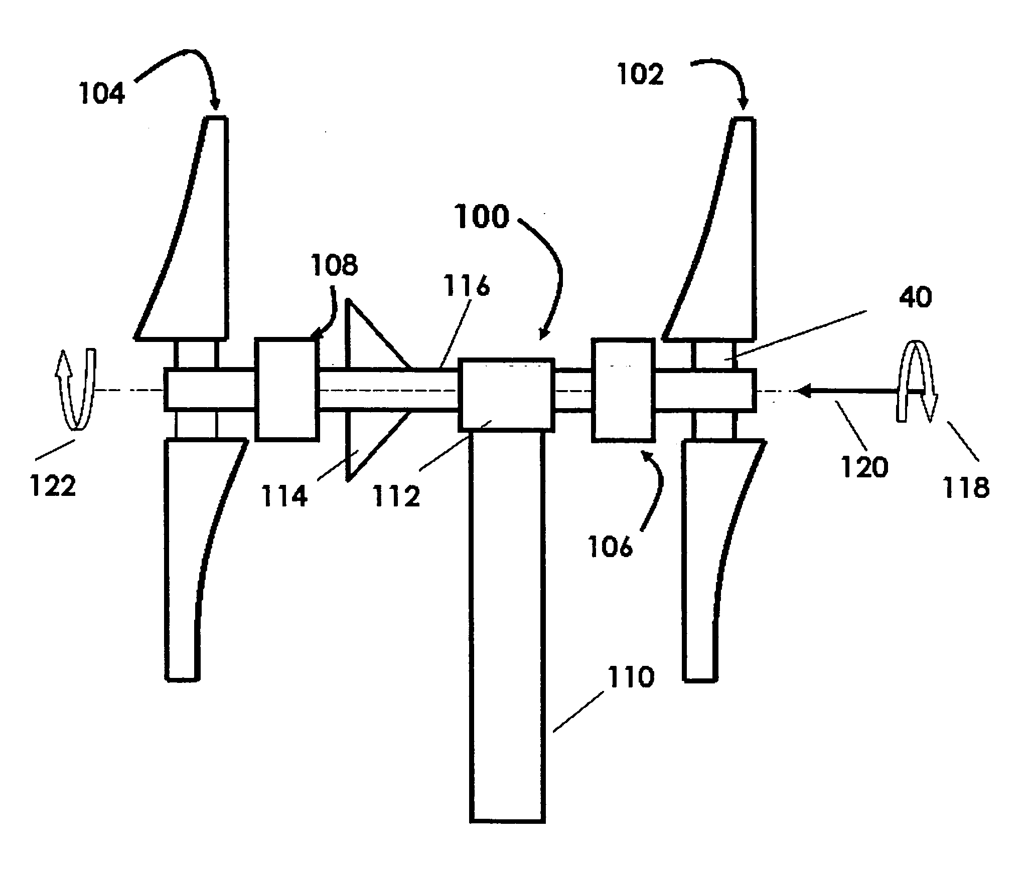
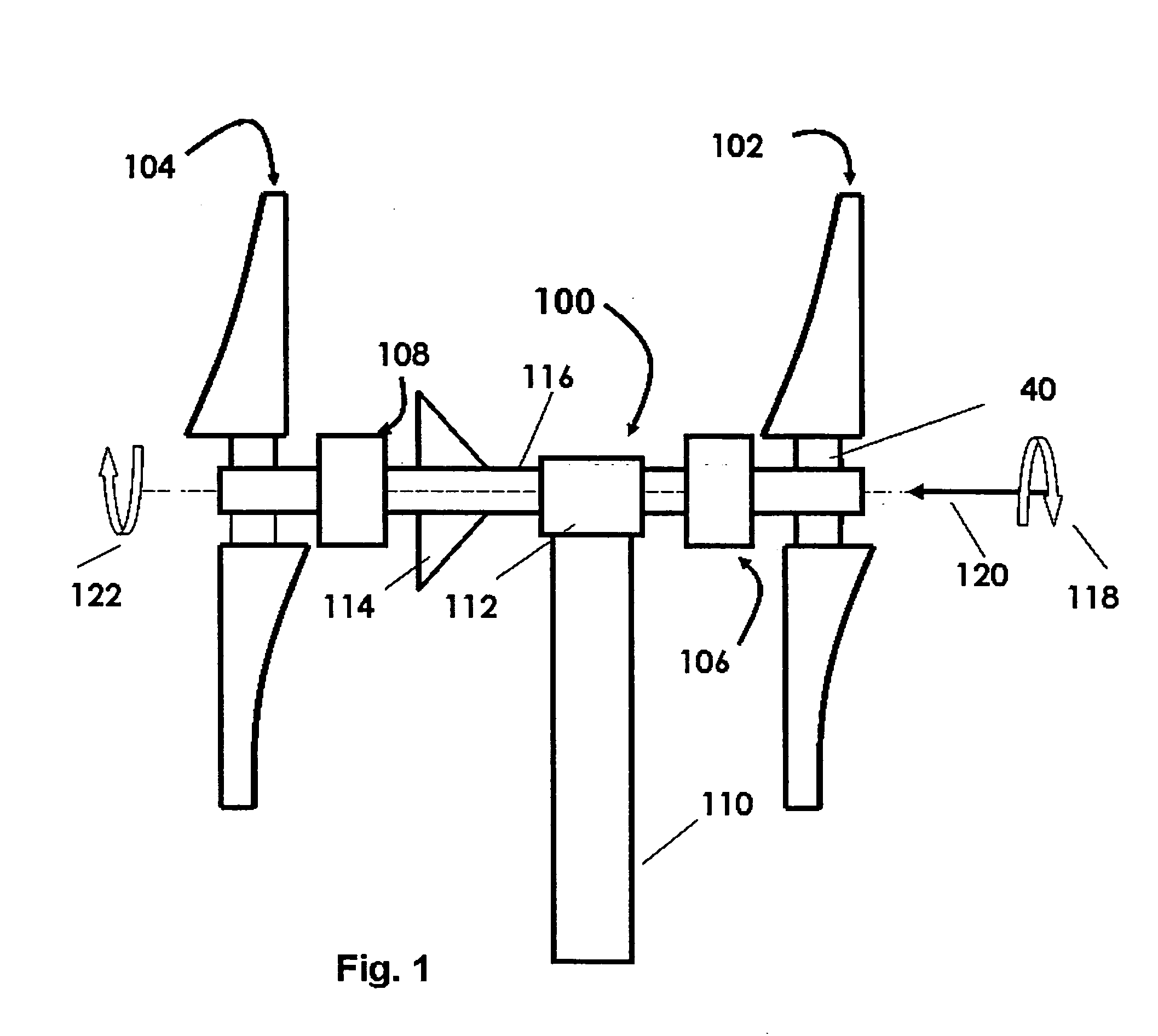
[0045]FIG. 1 shows a perspective view of a passively pitchable control device 100 incorporating the features of the present invention. Although the present invention will be described with reference to a single embodiment shown in the drawings, it should be understood that the present invention can be embodied in many alternate forms of embodiments. In addition, any suitable size, shape or type of elements or materials could be used. In FIG. 1, the passive pitch control device 100 is seen to include a camshaft 101 having half sine wave like groove (as depicted in FIG. 4), a cylindrical shell 13 supporting a blade assembly 102 and an axial compression spring 15.

[0046] A cross sectional view of the camshaft 101 is shown in FIG. 3, while a 3-D rendering is shown in FIG. 4. Two sliding surfaces 22a, 22b are provided to support the shell 13 and the blade assembly 102. The blade assembly and the shell are fastened together by means of se...


PUM


Abstract

“The present invention is for an apparatus and method for a passive pitchable device for wind turbines comprising: a camshaft having cam grooves engraved; a cylindrical shell; an axial compression spring; said blade assembly and said cylindrical shell are fastened together by screws; a plurality of balls that roll along said cam grooves, and convert the axial displacement to rotation or pitch angle; and wherein the passive pitchable device ensures said blades are at the optimum angle of incidence in the stationary position; as the rotor turns, the net force between centrifugal force on said blade and the resistant force from said compression spring causes the device to move axially outward while rotating to adjust the pitch of the rotor blade so that angle of incidence is optimal for the given wind speed; as the wind speed exceeds the design speed and the centrifugal force on the rotor blade continues to increase, the device continues the move axially outward while rotating in the opposite direction as to adjust the pitch of the blade in the opposite direction so that the rotor performance is controlled and severe dynamic loads are avoided”.

Description

FIELD OF THE INVENTION [0001] The present invention relates to a novel design of wind turbine blades in which there is a centrifugal force-controlled passive pitching device and forward swept blade tips. In low wind conditions this device enables feathering of the blade for easy starting of the rotor. In high wind conditions it controls the power imparted to the turbine to avoid encountering severe dynamic loads. The forward swept tips allow for noise reduction without sacrificing aerodynamic efficiency. DESCRIPTION OF PRIOR ART [0002] The present invention relates generally to the design, manufacture, and operation of passively pitchable wind turbine blades with respect to improving power extraction efficiency at all wind speeds, including low wind speed conditions. These innovations in particular are applicable to small wind turbines, large utility scale single rotor and contract rotor wind turbines. [0003] In recent years, it has become apparent that conventional methods of gener...

Claims


Application Information

Patent Timeline
Patent Type & Authority Applications(United States)
IPC IPC(8): F03D9/00
CPCF03D1/025F03D7/0224F05B2240/60Y02E10/723F05B2250/281F05B2260/77F05B2250/28Y02E10/72
Inventor APPA, KARLAPPA, SURL NARAYAN
Owner APPA KARL
Why Eureka
Try Eureka