Oxy-fuel combustion with integrated pollution control

a technology of pollution control and combustion, applied in the direction of heat recovery, indirect carbon-dioxide mitigation, solid removal, etc., can solve the problem of still a fairly substantial amount of emissions produced during the combustion process, and achieve the effect of reducing the volume of flue gas, preventing the introduction of air, and eliminating nox and condensable gases

Active Publication Date: 2007-09-06
JUPITER OXYGEN CORP
View PDF23 Cites 18 Cited by
  • Summary
  • Abstract
  • Description
  • Claims
  • Application Information

AI Technical Summary

Benefits of technology

[0007] An integrated oxygen fueled combustion system and pollutant removal system, reduces flue gas volumes, eliminates NOx and capture condensable gases. The system includes a combustion system having a furnace with at least one burner that is configured to substantially prevent the introduction of air. An oxygen supply supplies oxygen at a predetermine purity greater than 21 percent and a carbon based fuel supply supplies a carbon based fuel. Oxygen and fuel are fed into the furnace in controlled proportion to each other. Combustion is controlled to produce a flame temperature in excess of 3000 degrees F. and a flue gas stream containing CO2 and other gases and is substantially void of non-fuel borne nitrogen containing combustion produced gaseous compounds.
[0010] A method oxy-fuel combustion integrated with pollutant removal includes providing a furnace having at least one burner, and configured to substantially prevent the introduction of air, providing an oxygen supply for supplying oxygen at a predetermine purity greater than 21 percent and providing a carbon based fuel supply for supplying a carbon based fuel.

Problems solved by technology

Although oxy-fuel combustion provides fuel efficient and reduced emission energy generation, there is still a fairly substantial amount of emissions that are produced during the combustion process.

Method used


Image

  • Oxy-fuel combustion with integrated pollution control
  • Oxy-fuel combustion with integrated pollution control

Examples


Embodiment Construction

[0017] While the present invention is susceptible of embodiment in various forms, there is shown in the drawings and will hereinafter be described a presently preferred embodiment with the understanding that the present disclosure is to be considered an exemplification of the invention and is not intended to limit the invention to the specific embodiment illustrated. It should be further understood that the title of this section of this specification, namely, “Detailed Description Of The Invention”, relates to a requirement of the United States Patent Office, and does not imply, nor should be inferred to limit the subject matter disclosed herein.

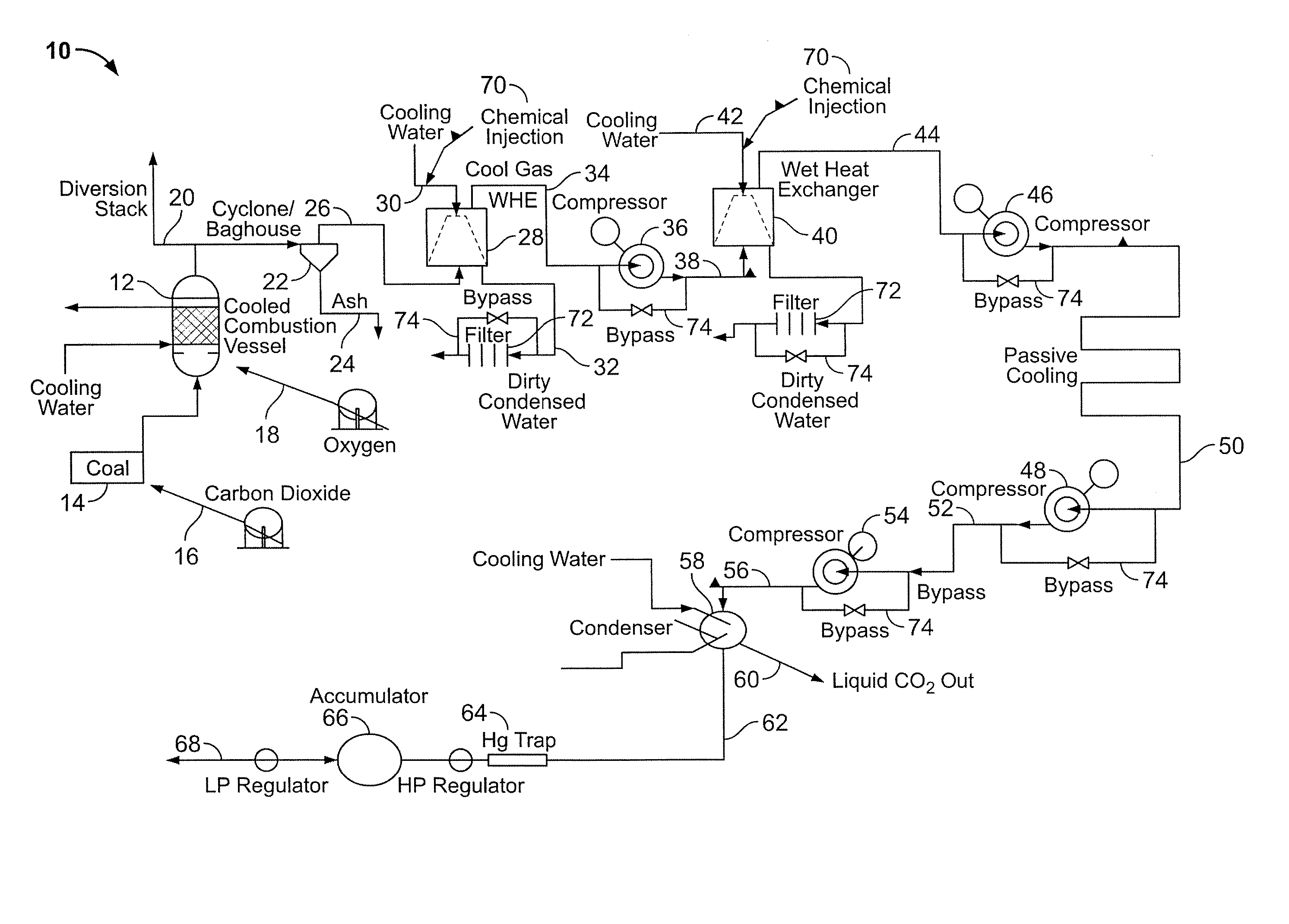
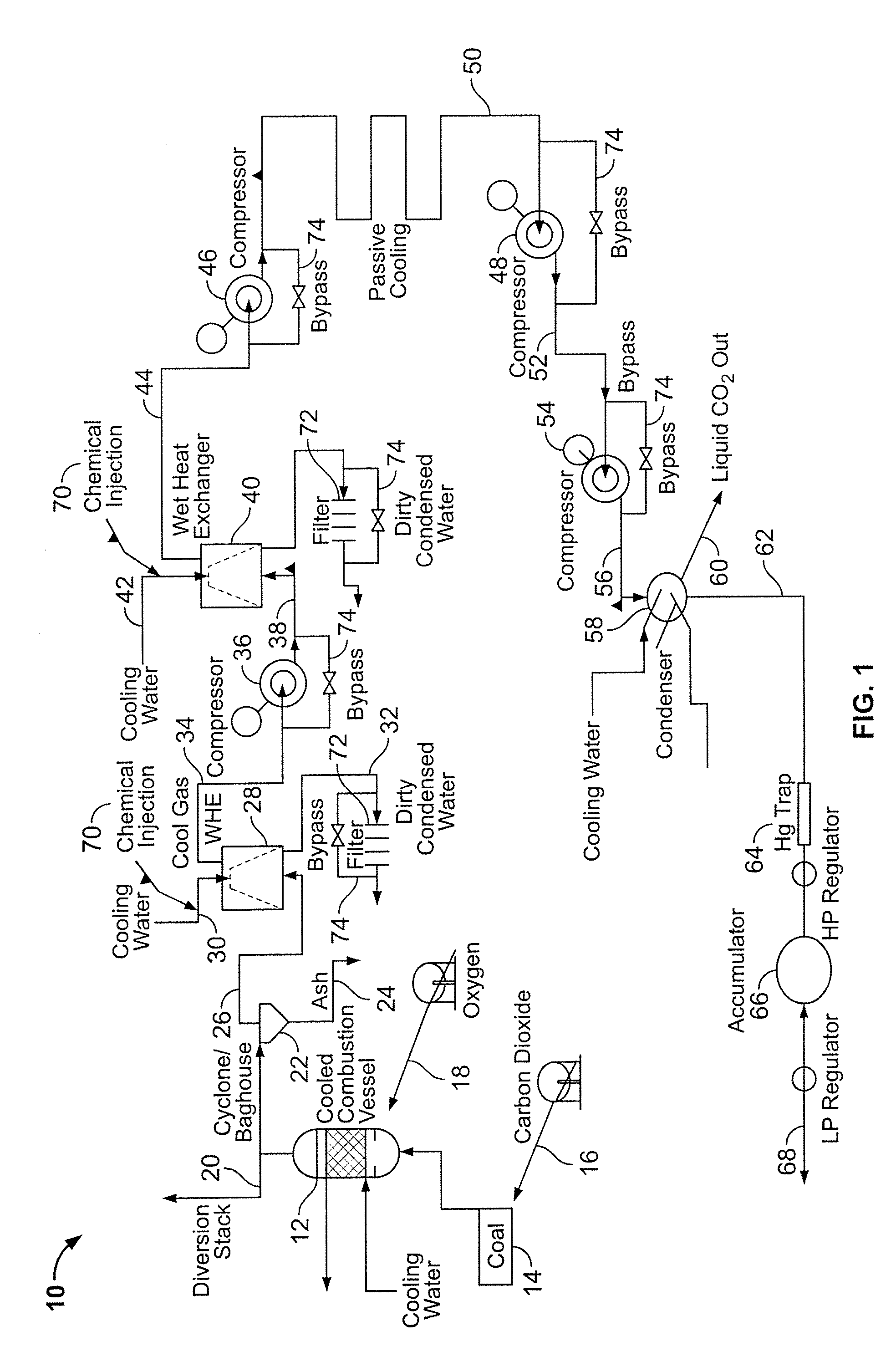
[0018] As discussed in the aforementioned patents to Gross, an oxy-fuel combustion system uses essentially pure oxygen, in combination with a fuel source to produce heat, by flame production (i.e., combustion), in an efficient, environmentally non-adverse manner. Oxygen, which is supplied by an oxidizing agent, in concentrations of about 85...


PUM

PropertyMeasurementUnit
temperatureaaaaaaaaaa
exit temperatureaaaaaaaaaa
pressureaaaaaaaaaa

Abstract

An oxygen fueled integrated pollutant removal and combustion system includes a combustion system and an integrated pollutant removal system. The combustion system includes a furnace having at least one burner that is configured to substantially prevent the introduction of air. An oxygen supply supplies oxygen at a predetermine purity greater than 21 percent and a carbon based fuel supply supplies a carbon based fuel. Oxygen and fuel are fed into the furnace in controlled proportion to each other and combustion is controlled to produce a flame temperature in excess of 3000 degrees F. and a flue gas stream containing CO2 and other gases. The flue gas stream is substantially void of non-fuel borne nitrogen containing combustion produced gaseous compounds. The integrated pollutant removal system includes at least one direct contact heat exchanger for bringing the flue gas into intimated contact with a cooling liquid to produce a pollutant-laden liquid stream and a stripped flue gas stream and at least one compressor for receiving and compressing the stripped flue gas stream.

Description

BACKGROUND OF THE INVENTION [0001] The present invention pertains to an integrated oxygen fueled combustion and pollution control system. More particularly, the present invention pertains to an oxy-fueled combustion system having integrated pollution control to effectively reduce, to near zero, emissions from combustion sources. [0002] Oxy-fueled combustion systems are known in the art. Such systems use essentially pure oxygen for combustion with fuel in near stoichiometric proportions and at high flame temperatures for high efficiency energy production. Oxy-fuel systems are used in boilers to produce steam for electrical generation and in industrial settings, such as in aluminum recycling to melt aluminum for recasting. It is also contemplated that oxy-fueled combustion can be used for waste incineration as well as other industrial and environmental applications. Oxy-fuel technology and uses for this technology are disclosed in Gross, U.S. Pat. Nos. 6,436,337, 6,596,220, 6,797,228 ...

Claims


Application Information

Patent Timeline
Patent Type & Authority Applications(United States)
IPC IPC(8): F23C5/00F23M3/02C01B32/50
CPCB01D53/002B01D2257/504F23J15/006F23J15/06F23J2900/15061F23D1/005F23L2900/07001Y02E20/322Y02E20/344Y02E20/363F23C9/00F23L7/007Y02E20/32Y02E20/34Y02E20/30F23C5/00F23M3/02
Inventor PATRICK, BRIAN R.
Owner JUPITER OXYGEN CORP
Why Eureka
Try Eureka