Transmission Type X-Ray Tube And Manufacturing Method Thereof

a technology of x-ray tubes and manufacturing methods, which is applied in the field of x-ray tubes, can solve the problems of difficult to lower the cost of manufacturing the conventional x-ray tubes, take a good amount of time to manufacture, and type x-ray tubes, etc., and achieves the effects of low cost, long lasting and high quality

Inactive Publication Date: 2007-09-13
HITACHI LTD
View PDF13 Cites 15 Cited by
  • Summary
  • Abstract
  • Description
  • Claims
  • Application Information

AI Technical Summary

Benefits of technology

[0012] In accordance with the invention related to claim 1, it is possible to braze the electrode lead, sealing member and exhaust tube all at once to the stem unit. Because the sealing member and the window frame are joined air-tightly by welding after the respective members are brazed, the step that involves the exposure of the cathode filament to high temperature during the production of the tubes is no longer necessary. This can also restrain the holding part between the cathode filament and the cathode lead from becoming loose since it does not get overheated. The invention had attained the production of a transmission type X-ray tube which is long lasting and high quality at a low cost while keeping the desired traits and long service life of the cathode filament.
[0013] In accordance with the invention relating to claim 2, the stem unit forming a cupped shape makes it easier to braze it to the sealing member, and because the height of the sealing member can be lowered the mechanical strength of completed X-ray tubes can be improved.
[0014] In accordance with the invention relating to claim 3, the joint of the stem unit and the sealing member can be blocked off from the electrode lead by a shield. For example, even when a metalized layer of the stem unit is evaporated while the tube is operating, the attachment of the evaporated

Problems solved by technology

Also, it is difficult to lower the cost in manufacturing the conventional X-ray tubes.
It takes a good amount of time to manufacture them since both stem side and X-ray window side requires brazing.
Also the operation process of the transmission type X-ray tube in Patent Document 2 is complicated since the brazing material used

Method used


Image

  • Transmission Type X-Ray Tube And Manufacturing Method Thereof
  • Transmission Type X-Ray Tube And Manufacturing Method Thereof
  • Transmission Type X-Ray Tube And Manufacturing Method Thereof

Examples


embodiment 1

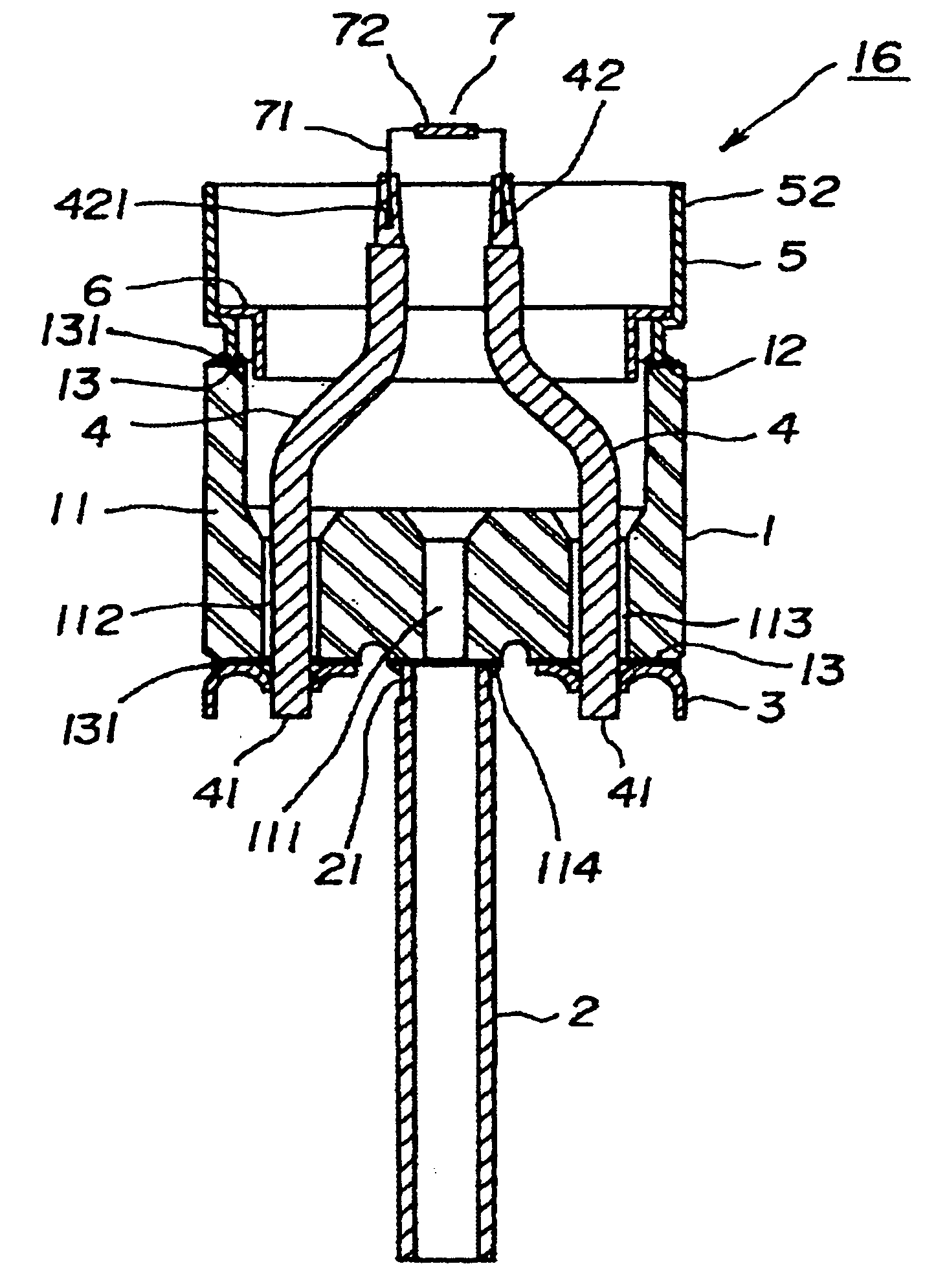
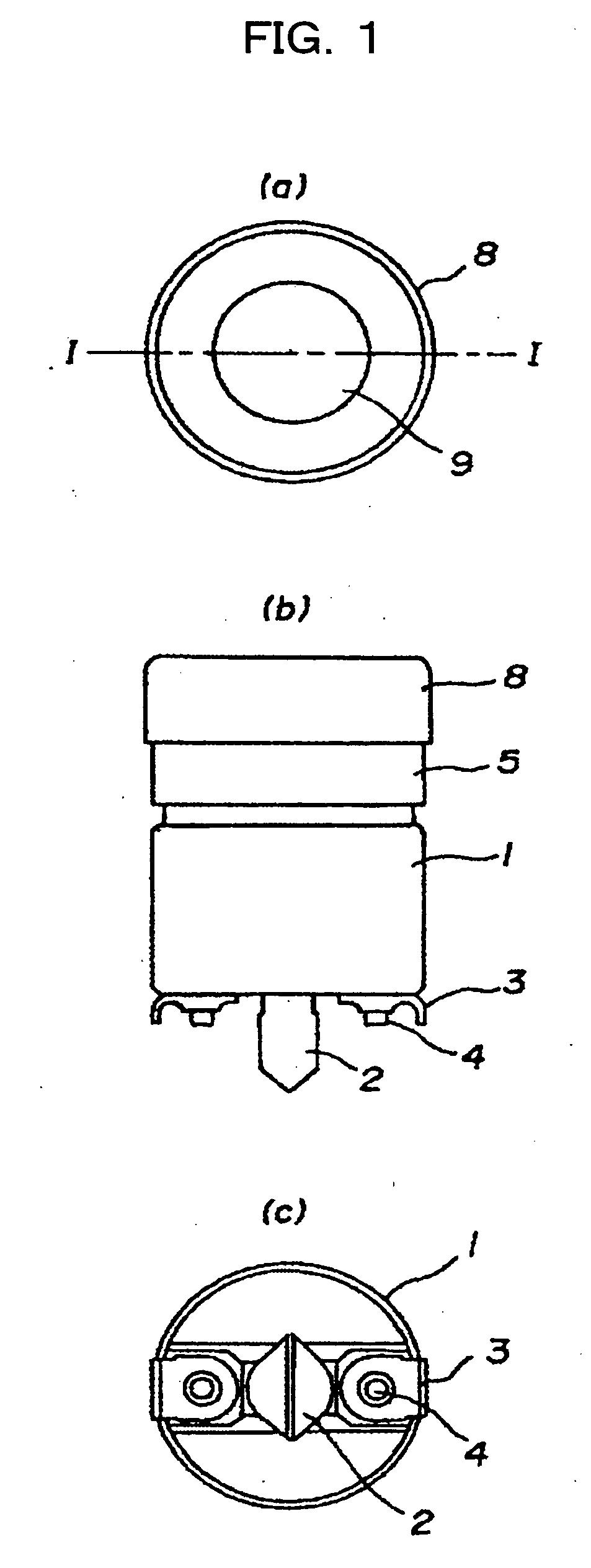
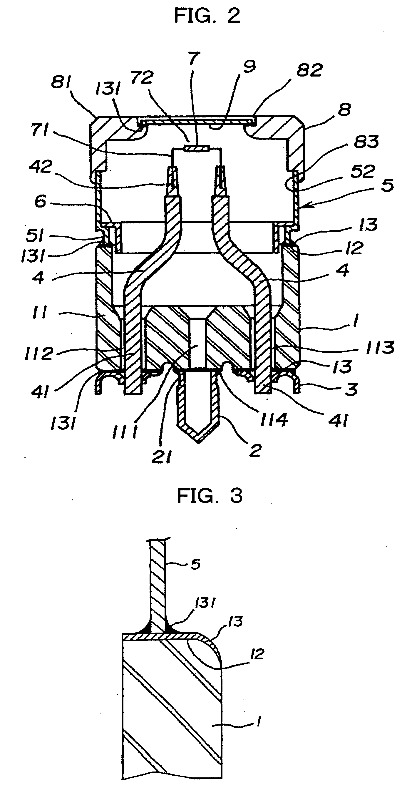
[0028]FIG. 1˜FIG. 3 are diagrams for illustrating embodiment 1 in the present invention of the transmission type X-ray tube. FIG. 1 (a) is a top view, FIG. 1 (b) is an elevational view, FIG. 1 (c) is a bottom view, FIG. 2 is a I-I line cross sectional view of FIG. 1 (a), and FIG. 3 is a partially enlarged view of FIG. 2.

[0029] In FIG. 1˜FIG. 3, 1 is a cupped stem unit formed by an insulating material such as ceramic, 2 is an exhaust tube, 3 is an end terminal, 4 is an electrode lead, 5 is a tube-like sealing member, 7 is a filament having the negative electrode acting as the electron-releasing source (hereinafter referred to as a cathode filament), 8 is a cupped window frame, 9 is an irradiating window, 12 is an open end of the stem unit, 13 is a metalized layer, 41 is one end of a lead wire, 42 is the other end of the lead wire, 51 is one end of the sealing member, 52 is the other end of the sealing member, 71 is a foot portion of the cathode filament, 72 is the electrode-releasin...

embodiment 2

[0042]FIG. 4 is a cross sectional view for illustrating embodiment 2 of the transmission type X-ray tube of the present invention, and the same encoding is used for the sections which are the same as the previously described diagram.

[0043] In FIG. 4, stem unit 10 is composed of a flat plate. Stem unit 10 has metalized layer 13 on top surface 101 and the bottom surface 102, and first tube 151 formed by insulating material of sealing member 15 is air-tightly welded to top surface 101. This sealing member 15 is configured with the addition of ceramic tube 152 and said first tube 151 to sealing member 5 of FIG. 3, and each of ceramic tube 152, sealing member 5 and first tube 151 are air-tightly welded. Also, end terminal 52 on window frame 8 side of said sealing member 15 is air-tightly welded to open end 83 of window frame 8.

[0044] In accordance with the configuration of embodiment 2, the configuration of the stem unit is simple which makes it easy to produce a large quantity at a lo...

embodiment 3

[0045]FIG. 5 is a cross sectional view for further illustrating embodiment 3 of the transmission type X-ray tube of the present invention, and the same encoding is used for the sections which are the same as the previously described diagram.

[0046] In FIG. 5, stem unit 20 is composed of a flat plate. Stem unit 20 has metalized layer 13 formed on its outer surface 202 and bottom surface 203 of its top surface 201 side, and cup 251 of sealing member assembly 25 is air-tightly welded to outer surface 202. Sealing member assembly 25 here is configured by said cups 251 being placed symmetrically on both sides holding the second ceramic tube 252 therebetween and each of them being air-tightly brazed. The end terminal 253 of cup 251 being placed on the side of said window frame 8 is air-tightly welded to open end 83.

[0047] In accordance with the configuration of embodiment 3, the configuration of the stem unit is simple and excels in productivity at a low cost. The reliability of the herm...


PUM


Abstract

A transmission type X-ray tube includes an electrode lead (4) holding a cathode filament (7) and a stem unit (1) to which a sealing member (5), an exhaust tube (2), and the like are attached by brazing, and an irradiation widow frame (8) having an X-ray irradiation window (9) attached by brazing.
The other end side (52) of the sealing member (5) is attached to an open end (83) of the irradiation window frame (8) by welding. Thus, it is possible to obtain a high-quality transmission type X-ray tube having a long service life at a low cost.

Description

FIELD OF INVENTION [0001] The present invention relates to an X-ray tube, and in particular to a transmission type X-ray tube and the manufacturing method thereof. BACKGROUND ART [0002] An X-ray tube is used as an X-ray source such as a medical X-ray device and a measuring device for industrial purposes. These X-ray tubes are classified broadly into rotating anode X-ray tubes and stationary anode X-ray tubes, and the previously mentioned transmission type X-ray tube belongs to the category of stationary anode X-ray tubes or to category of its own. [0003] Recently, as disclosed in Patent Document 1, X-ray tubes have extended use application to an X-ray source in static eliminator. [0004] Patent Document 1 relates to static eliminator and a method thereof for removing static electricity, and it removes static electricity on both sides of an object at the same time by radiating X-rays to the object. [0005] In this manner, a removal of static electricity has become a significant issue i...

Claims


Application Information

Patent Timeline
IPC IPC(8): H01J35/18H01J9/00H01J9/24H01J9/26H01J35/06H01J35/08H01J35/16
CPCH01J9/26H01J35/06H01J35/16H01J35/32H01J2235/186H01J2235/06H01J2235/087H01J2235/16H01J2235/023H01J35/116H01J35/186H01J35/066H01J35/064
Inventor ITO, YUICHIMORIIKE, TORUHOSOYA, SEIJIDAN, YOSHIHIKOOTSUKA, MAKOTO
Owner HITACHI LTD
Why Eureka
Try Eureka