

Color filter, method of fabricating the same and Liquid-Crystal Display device
- Summary
- Abstract
- Description
- Claims
- Application Information
AI Technical Summary
Benefits of technology
Problems solved by technology
Method used
Image

Examples
first embodiment
Color Filter of First Embodiment
[0199]The structure of a color filter for a LCD device according to a first embodiment of the present invention is shown in FIGS. 9B, 10A and 11A.
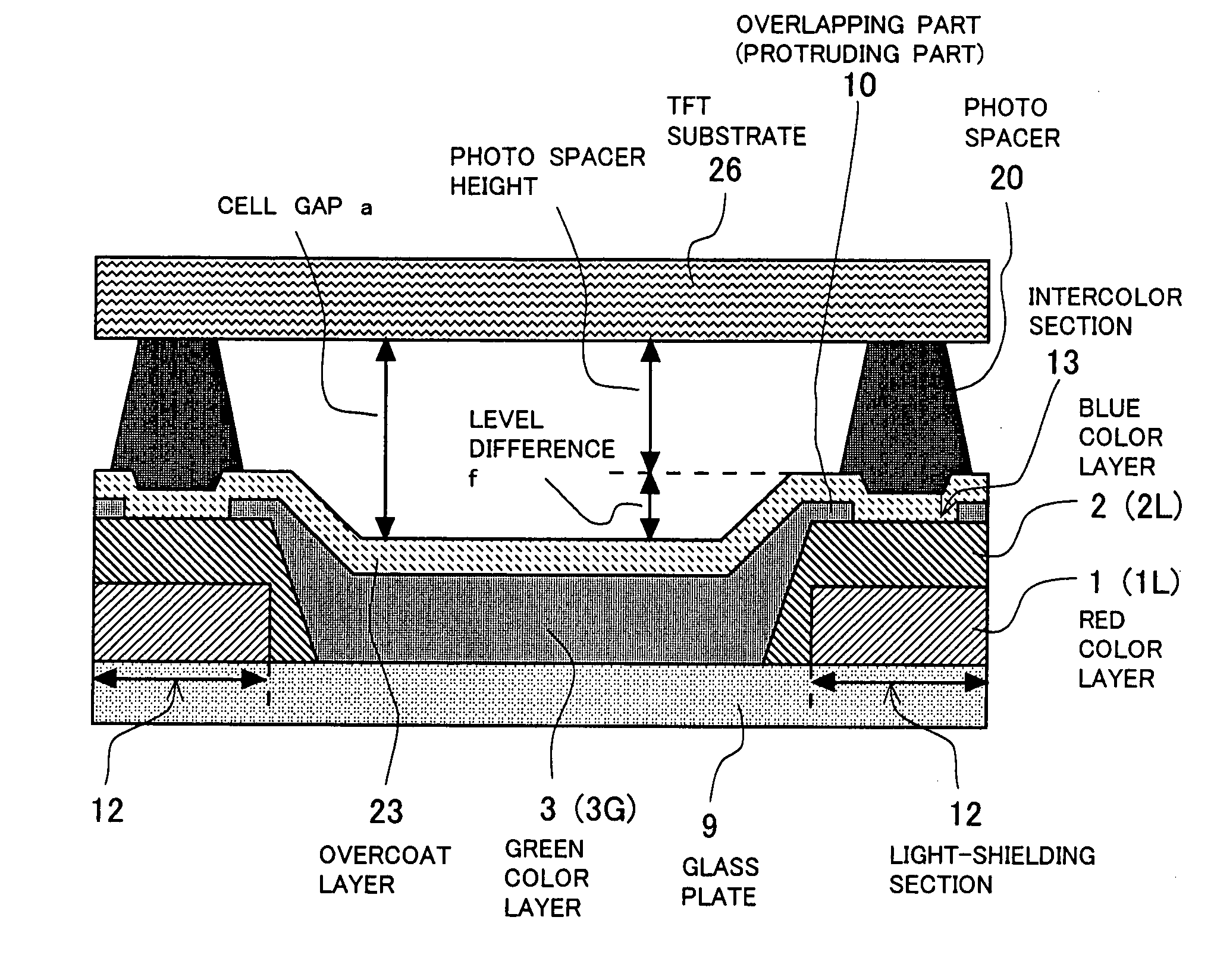
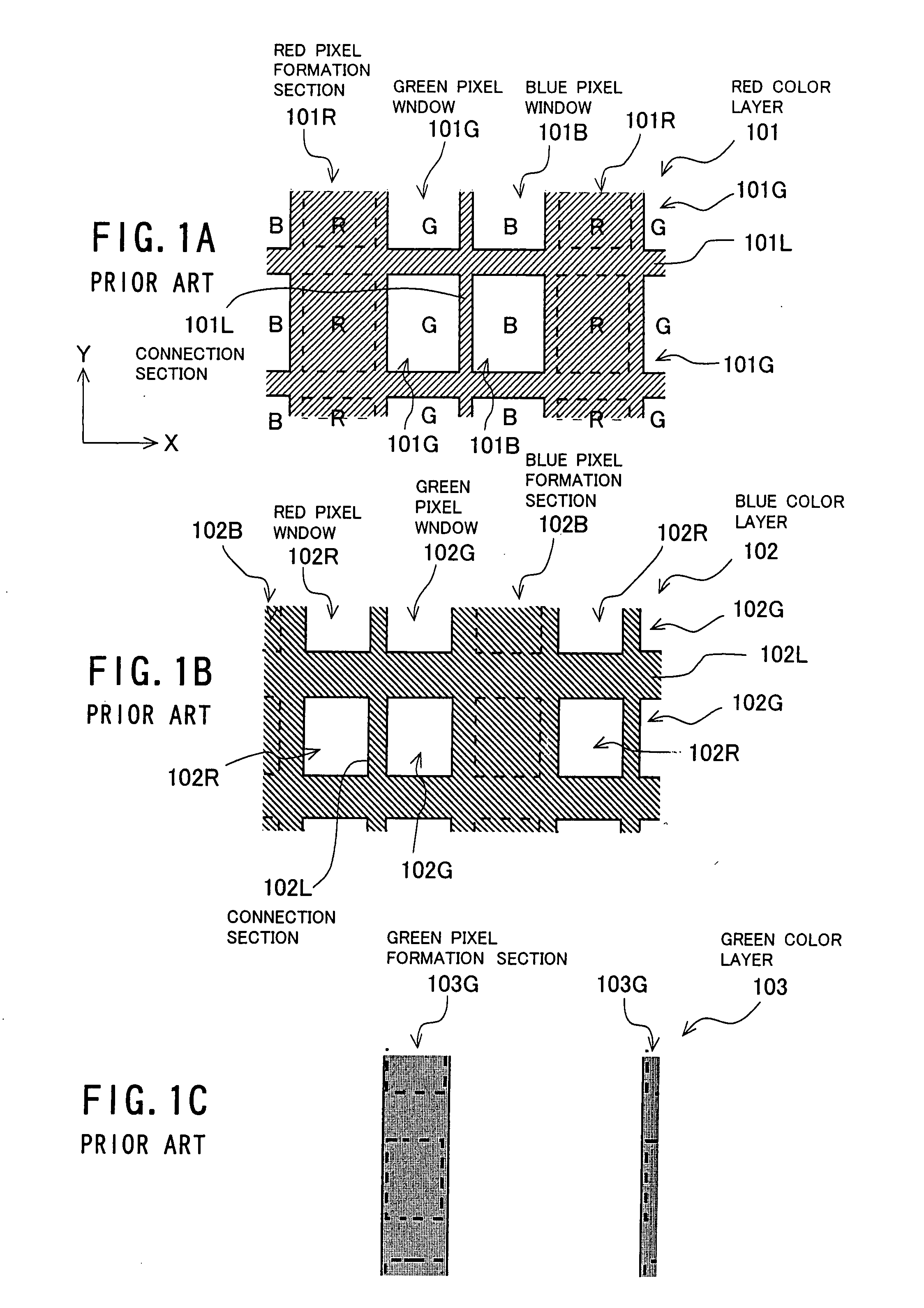
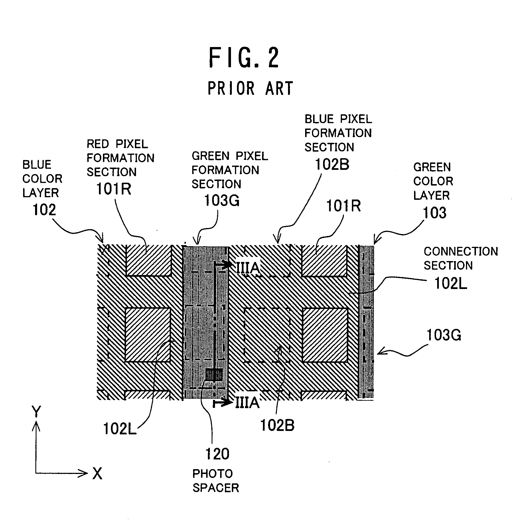
[0200]The color filter according to the first embodiment comprises a red color layer 1 having the pattern of FIG. 8A, a blue color layer 2 having the pattern of FIG. 8B, and a green color layer 3 having the pattern of FIG. 8C. The red, blue, and green color layers 1, 2, and 3 are overlapped with each other on the surface (i.e., the X-Y plane) of a transparent glass plate (i.e., a transparent support) 9. This color filter does not include a black matrix. The light-shielding function of a black matrix is realized by overlapping the red and blue color layers 1 and 2.
[0201]The red color layer 1 is formed on the surface of the glass plate 9. The layer 1 has stripe-shaped red pixel formation sections 1R and connection sections 1L, as shown in FIG. 8A.
[0202]The stripe-shaped red pixel formation sections 1R are exte...
second embodiment
Color Filter of Second Embodiment
[0258]The structure of a color filter for a LCD device according to a second embodiment of the present invention is shown in FIG. 20B. FIG. 20B is a partial plan view of the said color filter.
[0259]The color filter according to the second embodiment comprises a red color layer 1a having the pattern of FIG. 19A, a blue color layer 2a having the pattern of FIG. 19B, and a green color layer 3a having the pattern of FIG. 19C. The red, blue, and green color layers 1a, 2a, and 3a are overlapped on the surface (i.e., the X-Y plane) of a transparent glass plate (i.e., a transparent support) 9. This color filter does not include a black matrix. This point is the same as the above-described color filter according to the first embodiment. However, the color filter according to the second embodiment is different from that of the first embodiment in that (i) the light-shielding function in the vicinities of the scanning lines on the TFT substrate is realized by o...
example 1
[0311]First, a red-colored composite (which was generated by dispersing a red pigment in a transparent resin along with an optical initiator, a polymeric monomer, and a solvent) was coated on the surface of the glass plate 9 (the glass plate 71) to have a predetermined thickness with a spin coater. Then, the red-colored composite film thus formed was subject to a reduced-pressure drying process and a pre-bake process. Thereafter, the said film was selectively exposed using a photomask and then, was subjected to a developing process, a cleaning process with water, and a post-bake process, forming the red color layer 1 having the pattern of FIG. 8A.
[0312]Following this, in the same way as the red color layer 1 using a blue-colored composite, the blue color layer 2 having the pattern of FIG. 8B was formed to be overlapped with the red color layer 1.
[0313]Finally, in the same way as the red color layer 1 using a green-colored composite, the green color layer 3 having the pattern of FIG....
PUM
 Abstract
Description
Claims
Application Information