OFDM communication systems, transmitters and methods

a communication system and transmitter technology, applied in the field of orthogonal frequency division multiplexing (ofdm) communication systems and methods, can solve the problems of loss of orthogonality of sub-carriers, high peak-to-average power ratio (hereinafter papr), and large dynamic range in the transmitter, so as to achieve better performance

Inactive Publication Date: 2007-09-20
FUJITSU LTD
View PDF8 Cites 96 Cited by
  • Summary
  • Abstract
  • Description
  • Claims
  • Application Information

AI Technical Summary

Benefits of technology

[0098] It is envisaged that embodiments of the seventh to ninth aspects of the present invention may be applied to any OFDM transmitter as a tool for selecting a prospective OFDM signal from a set of prospective OFDM signals for transmission. That is, embodiments of the seventh to ninth aspects of the present invention may be used universally to replace, for example, the use of PAPR measurements to select signals. Simulations show that the use of an ACP value (as mentioned above) rather than a PAPR value as a tool for selecting a prospective OFDM signal produces a better performance in an OFDM transmitter, manifested for example in a reduced BER.

Problems solved by technology

One problem which arises in OFDM communication systems is that a peak-to-average power ratio (hereinafter PAPR) tends to be high.
When the PAPR is high, an amplifier having a very wide dynamic range is required in the transmitter, which is undesirable.
As is well known, in OFDM systems, orthogonality of sub-carriers is lost when multipath channels are involved.
However, increasing the number of sub-blocks increases the processing burden on the transmitter.
For example, the complexity of the search space for the best combination of IDFT output signals increases exponentially as the number of sub-blocks increases, which is generally prohibitive.
This in turn implies that immense processing power is required in the transmitter and that the signalling overhead for transmitting the identity ũ may be undesirably high.
Although it is possible to trade off additional receiver complexity with a reduction in the signalling overhead, for example by adopting a blind or semi-blind receiver, SLM methods involving high numbers of phase vectors are still complex and expensive to implement.
A further problem with SLM is that, because the set of phase vectors is determined on a random basis, it is unable to reach the ideal (PAPR free) performance, especially when the number of sub-carriers is large.
As a result, only one IFFT operation is needed and the complexity is relatively low.
Also, the number of required iterations is generally high (for example around 30 iterations are suggested in the above paper) and this leads to a high processing burden and / or high power consumption.

Method used


Image

  • OFDM communication systems, transmitters and methods
  • OFDM communication systems, transmitters and methods
  • OFDM communication systems, transmitters and methods

Examples


first embodiment

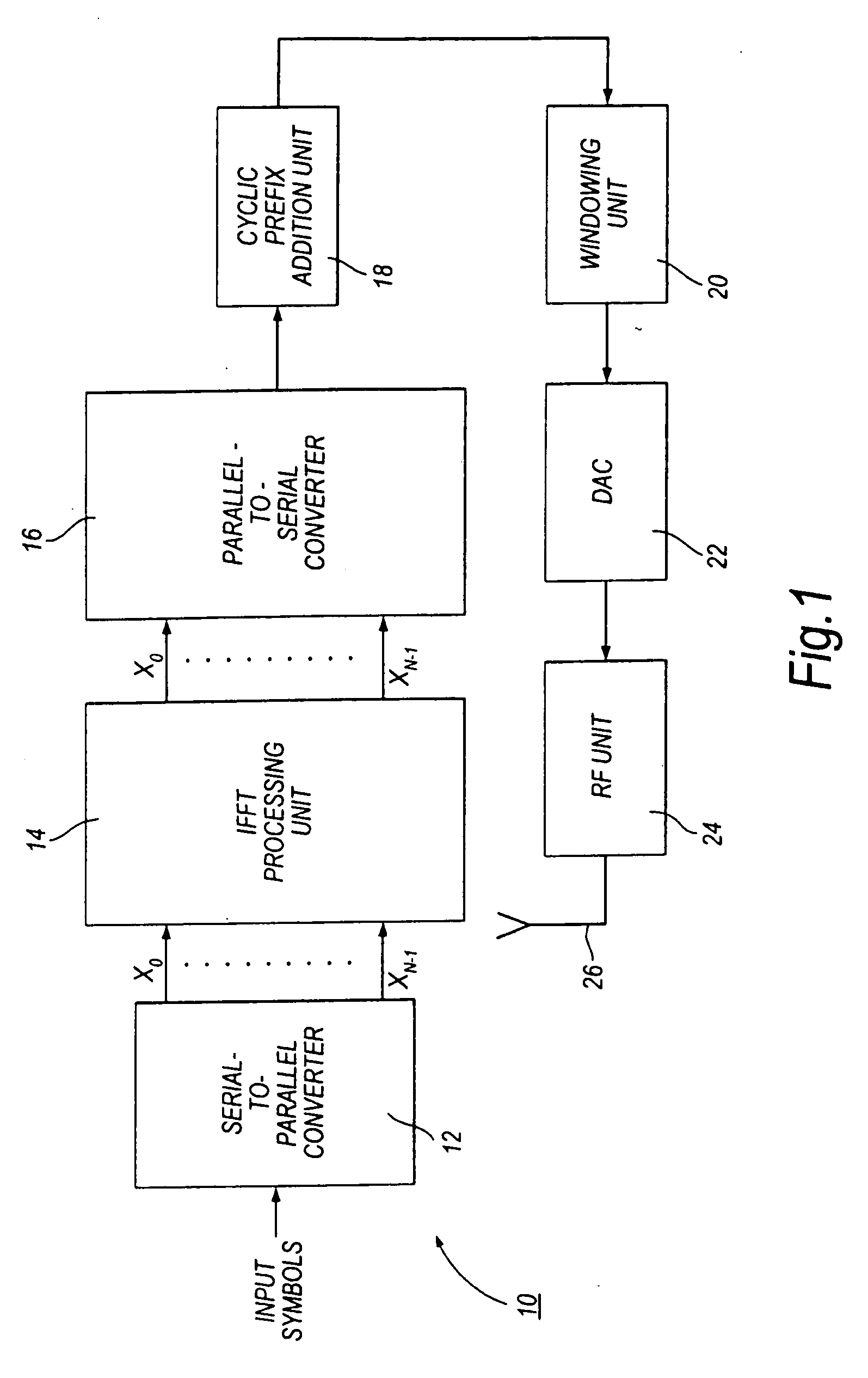
[0145]FIG. 5 shows parts of an OFDM transmitter according to the present invention. In this embodiment, it is assumed that the transmitter is adapted for wireless communication, but embodiments of the present invention are also applicable to communication systems having a wire connection between the transmitter and the receiver. The transmitter 100 is, for example, a node B of a wireless communication system, and the receiver (not shown) is, for example, a user equipment (UE) of such a wireless communication system.

[0146] In FIG. 5, elements which are the same as elements of the FIG. 1 transmitter described hereinbefore have been given the same reference numerals. The transmitter of FIG. 5 differs from the transmitter of FIG. 1 in that it includes a data allocation unit 102 and a control unit 104.

[0147] As in the FIG. 1 transmitter, a serial-to-parallel converter 12 receives serial input symbols which, in this embodiment, are assumed to comprise both data symbols DS and pilot symbo...

second embodiment

[0160] The use of circular data allocation as in the second embodiment has a number of advantages. A first advantage is that because the number of rotations is N, the maximum number of available allocations requiring calculation is also N, which is usually desirably small. Of course, not all possible rotation values need to be available. For example, the number of available rotations could be restricted to less than N. A second advantage is that the circular data allocation unit 112 can be implemented, either in hardware or in software, in a very simple manner. A third advantage is that, because the number of available rotations is at most N, the signalling overhead to signal the rotation value RCDA to the receiver (if required) as side information can be desirably small.

[0161] A further advantage which can be achieved when the allocations of input symbols to sub-carriers are rotations will be explained with reference to FIG. 7.

[0162] Firstly, referring to FIG. 6, the circular data...

third embodiment

[0173] The basic operation of the third embodiment is illustrated in FIG. 9. FIG. 9 shows how the group of input symbols and the rotational pilot symbol PSrot are allocated to the N sub-carriers for each of the rotation values r=0, r=1 and r=2. As can be seen from FIG. 9, when r=0, the rotational pilot symbol PSrot appears as symbol output RX0 and is allocated to sub-carrier 0. When r=1, the rotational pilot symbol PSrot appears as symbol output RX1 and is allocated to sub-carrier 1. When r=2, the rotational pilot symbol PSrot appears as symbol output RX2, and is allocated to sub-carrier 2. The group of N-2 input symbols (which, as noted above may include regular pilot symbols PSreg as well as data symbols) appear in order on the remaining sub-carriers following the sub-carrier to which the rotational pilot symbol PSrot is allocated.

[0174] At the or each receiver, as described later in more detail, the received signal is subjected to N-point fast Fourier transform (FFT) processing t...


PUM


Abstract

A transmitter 100 transmits an orthogonal frequency division multiplexing (OFDM) signal. A control unit 104 receives a group of input symbols (X0 to XN-1) based on which the transmitted signal is to be generated. The control unit selects, from among a plurality of available allocations of input symbols to sub-carriers, one allocation to apply to the received group of input symbols. Each available allocation serves to allocate the input symbols to respective sub-carriers in a different way from each other available allocation. The allocation selection is based on predicted values of a predetermined property, e.g. a peak-to-average power ratio (PAPR), of the transmitted signal for different available allocations. The available allocations may be different rotations. Further elements 102, 14, 16 of the transmitter generate the transmitted signal using the selected allocation.

Description

CROSS-REFERENCE TO RELATED APPLICATIONS [0001] This application claims priority from European patent application nos. 06251480.7 and 06251481.5 filed at the European Patent Office on 20 Mar. 2006, the contents of which are incorporated herein by reference. BACKGROUND OF THE INVENTION [0002] 1. Field of the Invention [0003] The present invention relates to orthogonal frequency division multiplexing (OFDM) communication systems and methods and to transmitters and transmitting methods for use in such systems. [0004] 2. Description of the Related Art [0005] An OFDM system is a type of multi-carrier transmission system, in which a single data stream is modulated onto N parallel sub-carriers, each sub-carrier signal having its own centre frequency. The sub-carriers are transmitted together as a single combined OFDM signal, the individual sub-carrier signals being recoverable in an OFDM receiver due to the orthogonal property of the sub-carriers. Typically, the number N of sub-carriers may...

Claims


Application Information

Patent Timeline
Patent Type & Authority Applications(United States)
IPC IPC(8): H04J11/00H04J1/00
CPCH04L27/2614H04L27/2608H04L5/0044
Inventor ABEDI, SAIED
Owner FUJITSU LTD
Why Eureka
Try Eureka