Laser diode stack end-pumped solid state laser

a laser and diode stack technology, applied in the field of end-pumped solid-state lasers, can solve the problems of low power of end-pumped lasers, excessive heat build-up, and high cost, and achieve good thermal coupling

Inactive Publication Date: 2007-09-20
NLIGHT PHOTONICS
View PDF30 Cites 20 Cited by
  • Summary
  • Abstract
  • Description
  • Claims
  • Application Information

AI Technical Summary

Benefits of technology

[0010] To provide package cooling, the laser diode stack is thermally coupled to a cooling block, the cooling block preferably including a slotted region into which the laser diode stack fits. In at least one preferred embodiment of the invention, thermally conductive and electrically isolating members are first bonded to the bottom and side surfaces of each submount and then bonded to the cooling block, the members being interposed between the laser diode stack and the cooling block. Preferably the cooling block is comprised of a pair of members, thus insuring good thermal coupling between the laser diode stack and the cooling block.

Problems solved by technology

End-pumped lasers are typically of lower power than side-pumped lasers due to the difficulty in coupling the output from multiple laser diodes into the relatively small end surface of the gain medium.
Although there are a variety of end-pumped, solid state laser configurations, typically they suffer from low power, excessive complexity and excessive heat build-up.

Method used


Image

  • Laser diode stack end-pumped solid state laser
  • Laser diode stack end-pumped solid state laser
  • Laser diode stack end-pumped solid state laser

Examples


Embodiment Construction

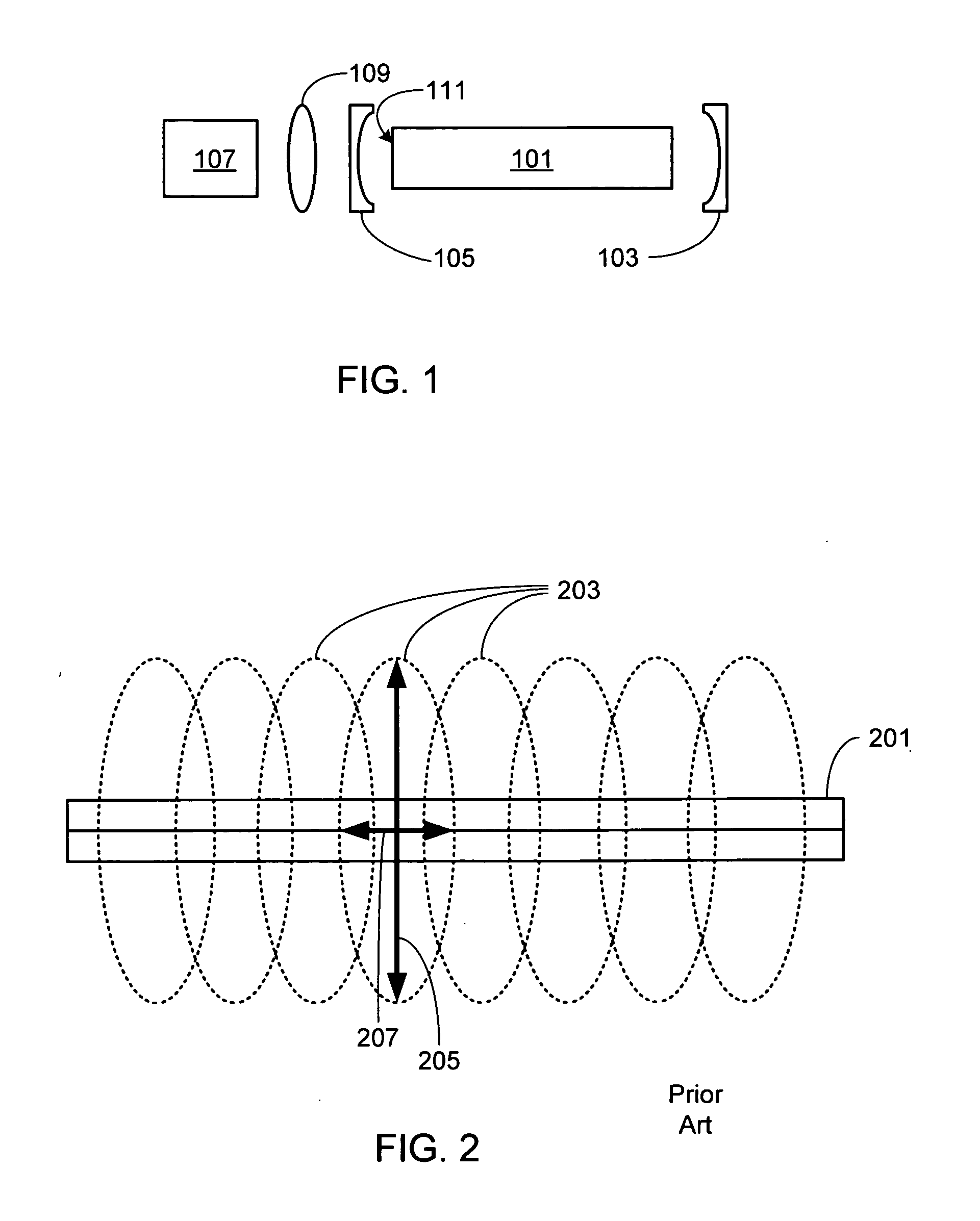
[0028]FIG. 1 is an illustration of a laser system in accordance with the invention. As shown, the laser cavity includes a laser gain medium 101, an output coupler 103 comprised of a partial reflector, and a rear reflector 105. Although in the illustrated example laser gain medium is cylindrically-shaped (i.e., a rod), it will be appreciated that the laser gain medium can be any appropriately doped glass or crystal of any shape, and that cylindrically-shaped and rectangularly-shaped (i.e., slab shaped) medium are but two exemplary shapes. It will also be appreciated that either one or both reflectors 103 and 105 can be separate from gain medium 101 as shown, or deposited directly onto the end surface or surfaces of the gain medium as is known by those of skill in the art. External to the laser cavity is at least one laser diode assembly 107 comprised of at least two laser diode subassemblies. As described in detail below, the laser diode subassemblies of assembly 107 do not utilize l...


PUM


Abstract

An end-pumped solid state laser utilizing a laser diode stack of laser diode subassemblies as the pump source is provided. The laser gain medium of the solid state laser is contained within a laser cavity defined by a pair of reflective elements. Each laser diode subassembly includes a submount to which one or more laser diodes are attached. The fast axis corresponding to each output beam of each laser diode is substantially perpendicular to the mounting surfaces of the submount. The laser diodes can be of one wavelength or multiple wavelengths. Preferably the submount has a high thermal conductivity and a CTE that is matched to that of the laser diode. On top of the submount, adjacent to the laser diode, is a spacer. The laser diode stack is formed by mechanically coupling the bottom surface of each submount to the spacer of an adjacent submount assembly. Preferably the laser diode stack is thermally coupled to a cooling block.

Description

CROSS-REFERENCE TO RELATED APPLICATION [0001] This application is a continuation-in-part of U.S. patent application Ser. No. 11 / 384,940, filed Mar. 20, 2006, the disclosure of which is incorporated herein by reference for any and all purposes.FIELD OF THE INVENTION [0002] The present invention relates generally to semiconductor lasers and, more particularly, to an end-pumped solid state laser utilizing a laser diode stack as the pump source. BACKGROUND OF THE INVENTION [0003] High power laser diodes, due to their size, efficiency and wavelength range, are well suited for pumping high power solid state lasers. In such laser systems the output from one or more laser diodes is coupled into a laser gain medium, the gain medium contained within a laser cavity defined by a pair of mirrors or reflective coatings disposed at either end of the medium. The laser diode output may be coupled into either an end surface of the gain medium, creating an end-pumped laser, or into one or more side su...

Claims


Application Information

Patent Timeline
Patent Type & Authority Applications(United States)
IPC IPC(8): H01S3/04H01S5/00
CPCH01S5/02264H01S5/4025H01S5/024H01S5/02272H01L2224/48091H01L2224/49111H01L2224/49175H01S3/09415H01S5/02469H01S5/4087H01S3/061H01S5/4037H01S5/02365H01S5/0237H01L2924/00012
Inventor DEFRANZA, MARK JOSEPHDAWSON, DAVID CLIFFORDFARMER, JASON NATHANIEL
Owner NLIGHT PHOTONICS
Why Eureka
Try Eureka