Wireless client device

a client device and wireless technology, applied in the field of wireless client devices, can solve the problems of not being able to meet the large transmission capacity needed for carrying video, requiring significant bandwidth for transmitting primarily video information to individual seats inside the aircraft, and reducing the cost of changing the seating configuration. the effect of short time, reduced cost and improved operating ra

Active Publication Date: 2007-09-20
PANASONIC CORP
View PDF5 Cites 14 Cited by
  • Summary
  • Abstract
  • Description
  • Claims
  • Application Information

AI Technical Summary

Benefits of technology

[0015] The wireless client device of the present invention enables wirelessly transmitting data signals to each seat. As a result, changing the wiring is not necessary when the seating configuration is changed, the seating configuration can therefore be changed in a short time, the operating rate of the aircraft can be improved, and the cost of changing the seating configuration is reduced. Furthermore, by disposing a wireless shield unit in the seat portion and disposing the antenna below the seat portion, MIMO decoding in an environment dominated by indirect waves is possible. As a result, signals can be stably received in the congested environment inside an airplane that is relatively hostile to wireless communication, and high quality video programming can therefore be provided without interruption.

Problems solved by technology

However, because changing the seating configuration means that the relay lines in the side walls must also be changed, changing the seating arrangement takes a long time and is thus expensive.
Transmitting primarily video information to individual seats inside an aircraft requires significant bandwidth.
The technologies taught in reference patents 1 and 2, however, are directed to carrying voice and data traffic within a building or facility and are not suited to the large transmission capacity needed to carry video.
The inside of an airplane is also a difficult environment for enabling stable wireless transmission because the aircraft is populated by several hundred seats and the seating configuration can change frequently.
As a result, the technologies taught in reference patents 1 and 2 cannot be used to wirelessly transmit high capacity video signals in an in-flight entertainment system with the high quality and stability that are required.

Method used


Image

  • Wireless client device
  • Wireless client device
  • Wireless client device

Examples


first embodiment

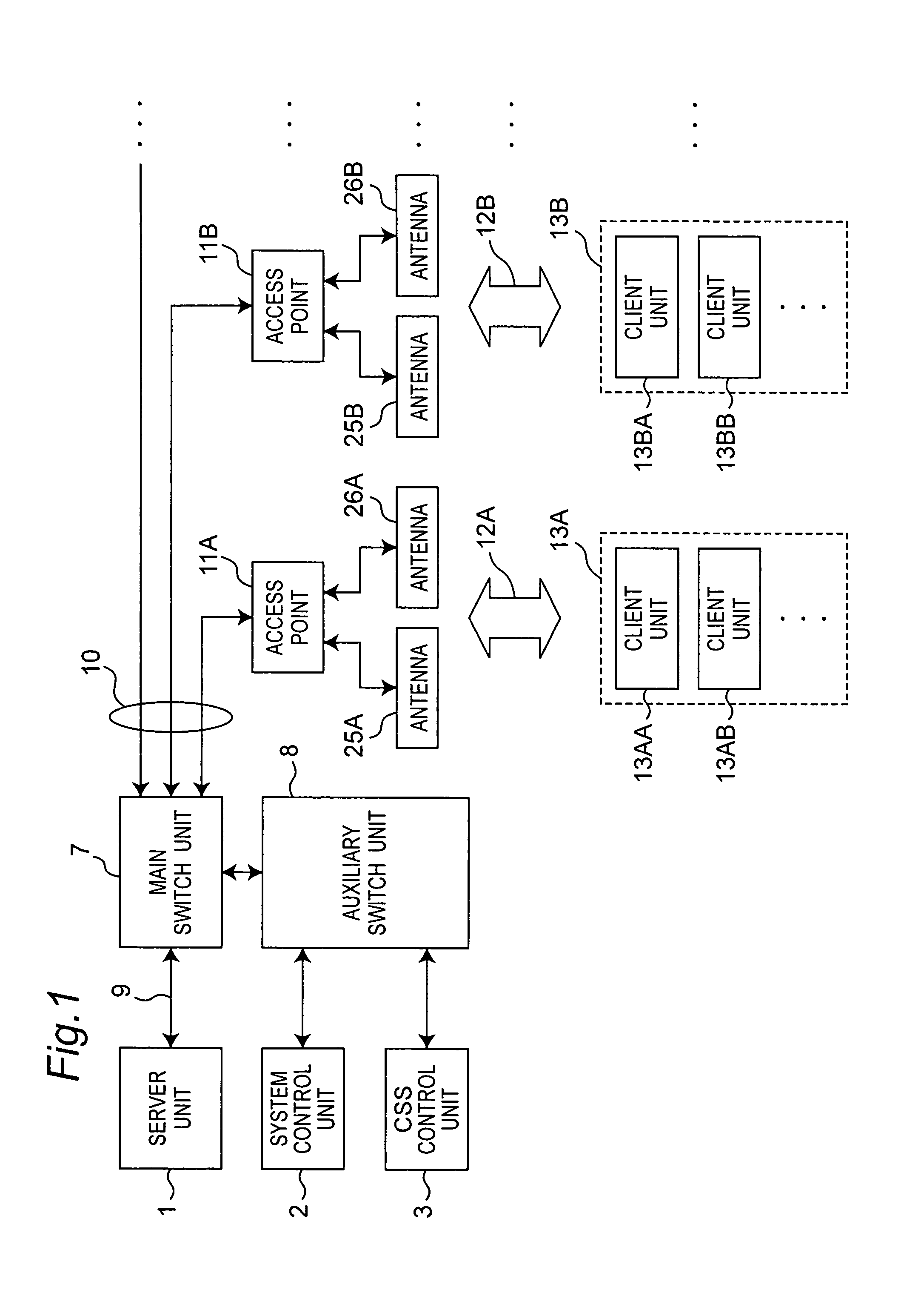
[0024]FIG. 1 is a block diagram showing the general arrangement of the first embodiment of the invention. This first embodiment of the invention is installed inside an aircraft. The aircraft may be an airplane with jet engines or propellers, for example, a helicopter, a hovercraft, a balloon tethered to the ground, a rocket, a man-made satellite, a space station, or any other type of craft that can remain aloft at a predetermined distance or more from the Earth's surface for at least a predetermined period of time. This first embodiment of the invention is described using a passenger plane by way of example only. There may be several hundred passenger seats installed in the airplane, and passengers can enjoy movies, audio programming, games, and Internet browsing by an in-flight entertainment (IFE) system.

[0025] Referring to FIG. 1, the server unit 1 includes a hard disk array for storing data signals including at least one of a video signal or an audio signal, and an AV server for...

second embodiment

[0064] The arrangement of the client unit in this second embodiment of the invention is described with reference primarily to the differences with the first embodiment. Other aspects of the arrangement, operation, and effect of this embodiment are the same as the first embodiment, and further description thereof is omitted.

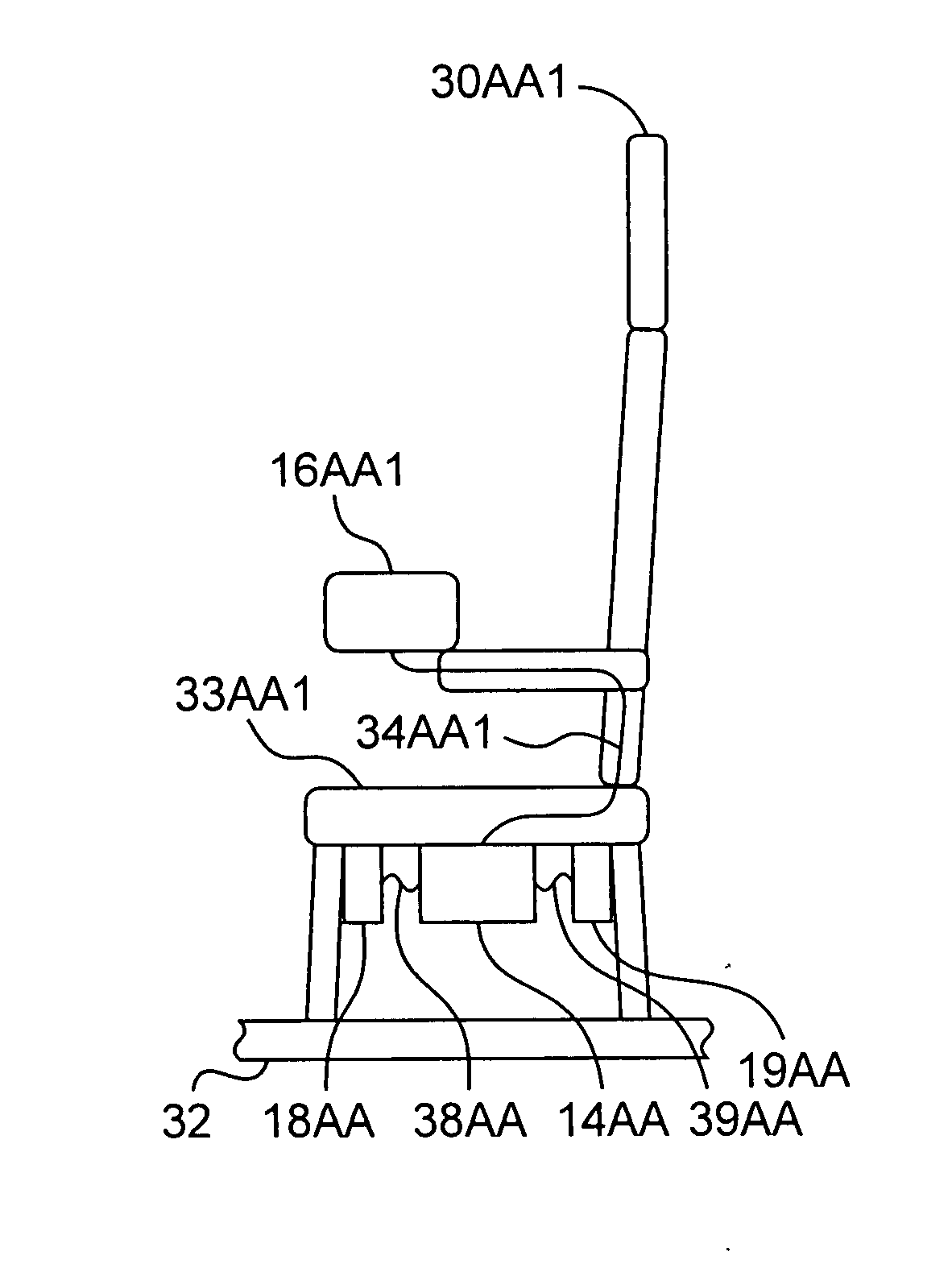
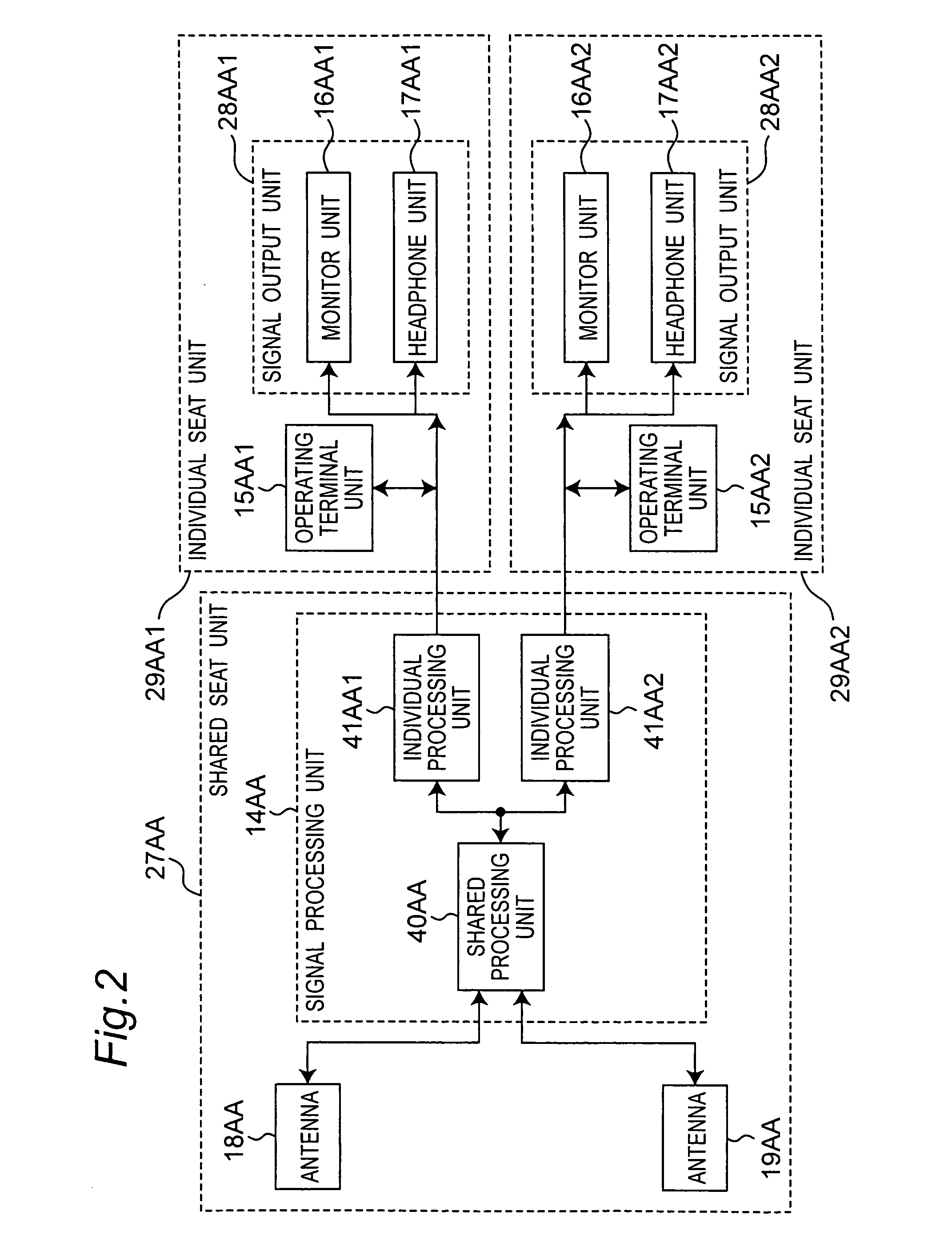
[0065]FIG. 5A and FIG. 5B schematically show the physical arrangement of the parts shown in the block diagrams in FIG. 1 and FIG. 2 in this second embodiment of the invention. FIG. 5A is a front view and FIG. 5B is a side view. Only the location of antenna 19AA and wire 39AA differ from the arrangement shown in FIG. 4A and FIG. 4B, and the configuration of this embodiment is otherwise the same as the first embodiment.

[0066] Antennae 18AA and 19AA are installed below the seat cushion 33AA1 and 33AA2 of seats 30AA1 and 30AA2, respectively, and are connected to the signal processing unit 14AA by wire 38AA and wire 39AA. As will be known from the front view in FIG. ...


PUM


Abstract

Because wired connections make changing the seating configuration difficult, a wireless client device enables stable wireless transmission. The wireless client device wirelessly transmits to and receives data signals from an access point inside an aircraft. The wireless client device has a seat unit with a seat portion on which aircraft passengers sit, an antenna for sending and receiving the data signals, a signal processing arrangement operable to handle data signal receiving and transmitting processes, and a signal output arrangement operable to output processed reception signals. The antenna arrangement, signal processing arrangement, and signal output arrangement are disposed to the seat unit.

Description

BACKGROUND OF THE INVENTION [0001] 1. Field of technology [0002] The present invention relates to technology for stably wirelessly transmitting large amounts of data in an airplane or other type of aircraft. [0003] 2. Description of Related Art [0004] In-flight entertainment (“IFE”) systems used in passenger planes in recent years have helped make long-distance flights more enjoyable by providing passengers with in-flight entertainment services such as movies, audio programming, games, and even Internet browsing. The movies, audio programming, Internet data, and other information accessible by these systems are typically stored in an on-board server, and delivered from the server by coaxial cable, optical fiber, or other wired medium as either analog or digital transmissions. IFE equipment generally includes a ceiling-mounted projector and an LCD or other type of video monitor, as well as compact, individual monitors and controllers (handsets) installed at individual passenger seats...

Claims


Application Information

Patent Timeline
Patent Type & Authority Applications(United States)
IPC IPC(8): H04B1/00B64D11/00H04B1/38H04B1/3822H04B7/04H04J99/00
CPCH04W16/18
Inventor TAKEUCHI, TOMOTAKAHIGASHIDA, MASAAKIEZAKI, TOSHIHIROSAKANISHI, YASUAKI
Owner PANASONIC CORP
Why Eureka
Try Eureka