Heat treating apparatus, heat treating method, and storage medium

Inactive Publication Date: 2007-09-20
TOKYO ELECTRON LTD
View PDF5 Cites 31 Cited by
  • Summary
  • Abstract
  • Description
  • Claims
  • Application Information

AI Technical Summary

Benefits of technology

[0020]Further, when the heat treating apparatus is separated from the installation place, since a trouble of leaking the cooling liquid is not generated, the heat treating apparatus can be easily maintained or exchanged.
[0021]Further, due to a structure in which a heat radiating fin unit is provided in the circulation passage of the cooling liquid as a heat ra

Problems solved by technology

On the other hand, in the conventional heat treating apparatus, the wafer mounted onto the cooling plate is cooled by flowing a cooling liquid in a cooling pipe provided in the interior of or at a lower portion of the cooling plate, which complicates the structure of the cooling plate and increase the size of the heat treating apparatus.
Then, since a cooling medium remains in the heat exchanging unit, the cooling medium

Method used


Image

  • Heat treating apparatus, heat treating method, and storage medium
  • Heat treating apparatus, heat treating method, and storage medium
  • Heat treating apparatus, heat treating method, and storage medium

Examples


Embodiment Construction

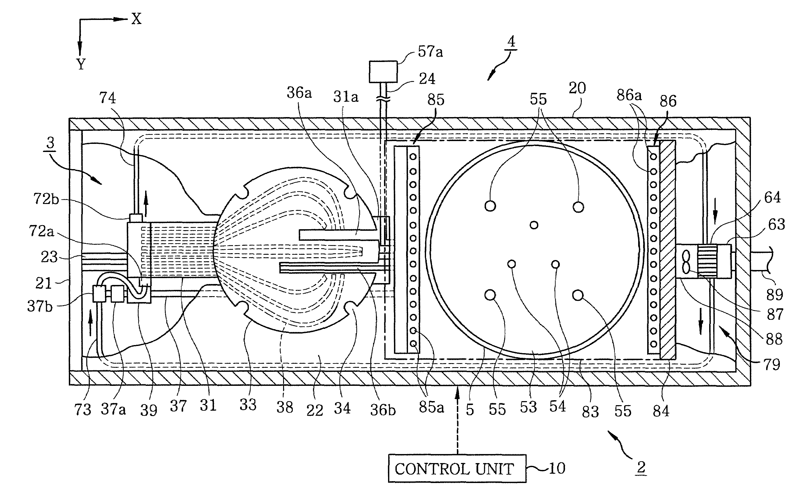
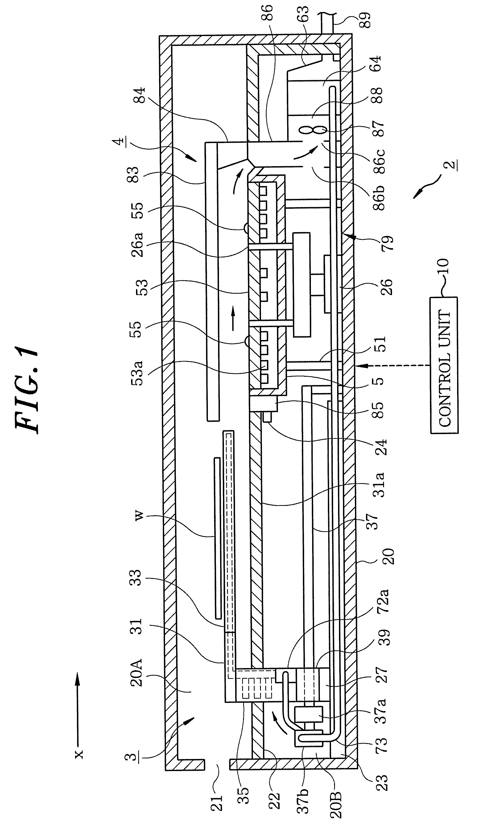
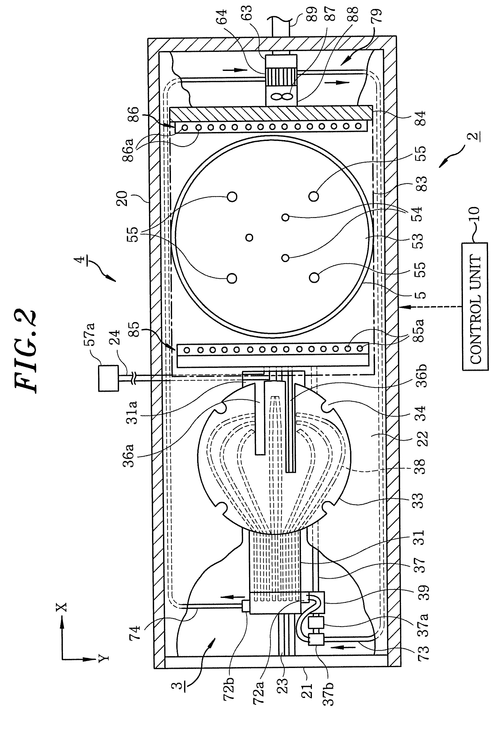
[0036]Hereinafter, as an example of an embodiment of a heat treating apparatus 2 performing a heat treating method according to the present invention, a heat treating apparatus forming a resist film on a surface of a semiconductor wafer (hereinafter, referred to as wafer) W by heat treating the wafer W which is a substrate the surface of which is coated with a liquid resist as a coating liquid will be described with reference to FIGS. 1 and 2.

[0037]The heat treating apparatus 2 can be mounted to and separated from a shelf installed in a coating and developing apparatus which will be described later and is stacked in the shelf so as to have multiple steps. Further, in the state in which the heat treating apparatus 2 is separated from the shelf, a housing 20 does not have an upper surface and both side surfaces. On the other hand, in the state in which the heat treating apparatus 2 is mounted to the shelf, a partitioning plate horizontally provided in the shelf and both side surfaces ...


PUM


Abstract

A heat treating apparatus includes a heating plate for heating a substrate coated with a coating liquid, a cooling plate for cooling the substrate and a heat pipe provided in the cooling plate, a cooling chamber being moved together with the cooling plate by the drive mechanism and accommodating a cooling liquid for cooling one end side of the heat pipe. The apparatus further includes a circulation passage provided in the heat treating apparatus to circulate the cooling liquid in the cooling chamber, a circulation pump for circulating the cooling liquid in the circulation passage; and a heat radiating member provided on the circulation passage to radiate the heat received by the cooling chamber to the outside of the heat treating apparatus.

Description

FIELD OF THE INVENTION[0001]The present invention relates to a heat treating apparatus including a heating plate heating a substrate, e.g., a semiconductor wafer, coated with a coating liquid, such as, and a cooling plate conveying the heated substrate, and a heat treating method.BACKGROUND OF THE INVENTION[0002]A coating and developing apparatus for coating a resist to a substrate and developing the substrate after exposure is used as an apparatus for forming a resist pattern on a substrate such as a semiconductor wafer or a glass substrate for a liquid crystal display (LCD). A heat treating apparatus called bake apparatus is employed in the coating and developing apparatus. For example, an apparatus for heating a substrate coated with a liquid resist takes a role in drying a solvent in the liquid resist.[0003]An example of such a heat treating apparatus 100 is shown in FIG. 13. The heat treating apparatus 100 is divided into an upper chamber 102 and a lower chamber 103 which are p...

Claims


Application Information

Patent Timeline
IPC IPC(8): F27B9/12C23C16/00H01L21/31
CPCF27B5/04F27B17/0025H01L21/68707H01L21/67178H01L21/6719H01L21/67109H05B1/0233
Inventor MATSUOKA, NOBUAKI
Owner TOKYO ELECTRON LTD
Why Eureka
Try Eureka