Surgical procedure and instrumentation for intrastromal implants of lens or strengthening materials

a technology of intrastromal implants and surgical procedures, applied in the field of intrastromal implants, can solve problems such as weakening of the structural integrity of the cornea, and achieve the effects of high permeability to oxygen and glucose, sufficient structural strength, and high strength and elasticity

Inactive Publication Date: 2007-09-20
YAHAGI TORU
View PDF7 Cites 43 Cited by
  • Summary
  • Abstract
  • Description
  • Claims
  • Application Information

AI Technical Summary

Benefits of technology

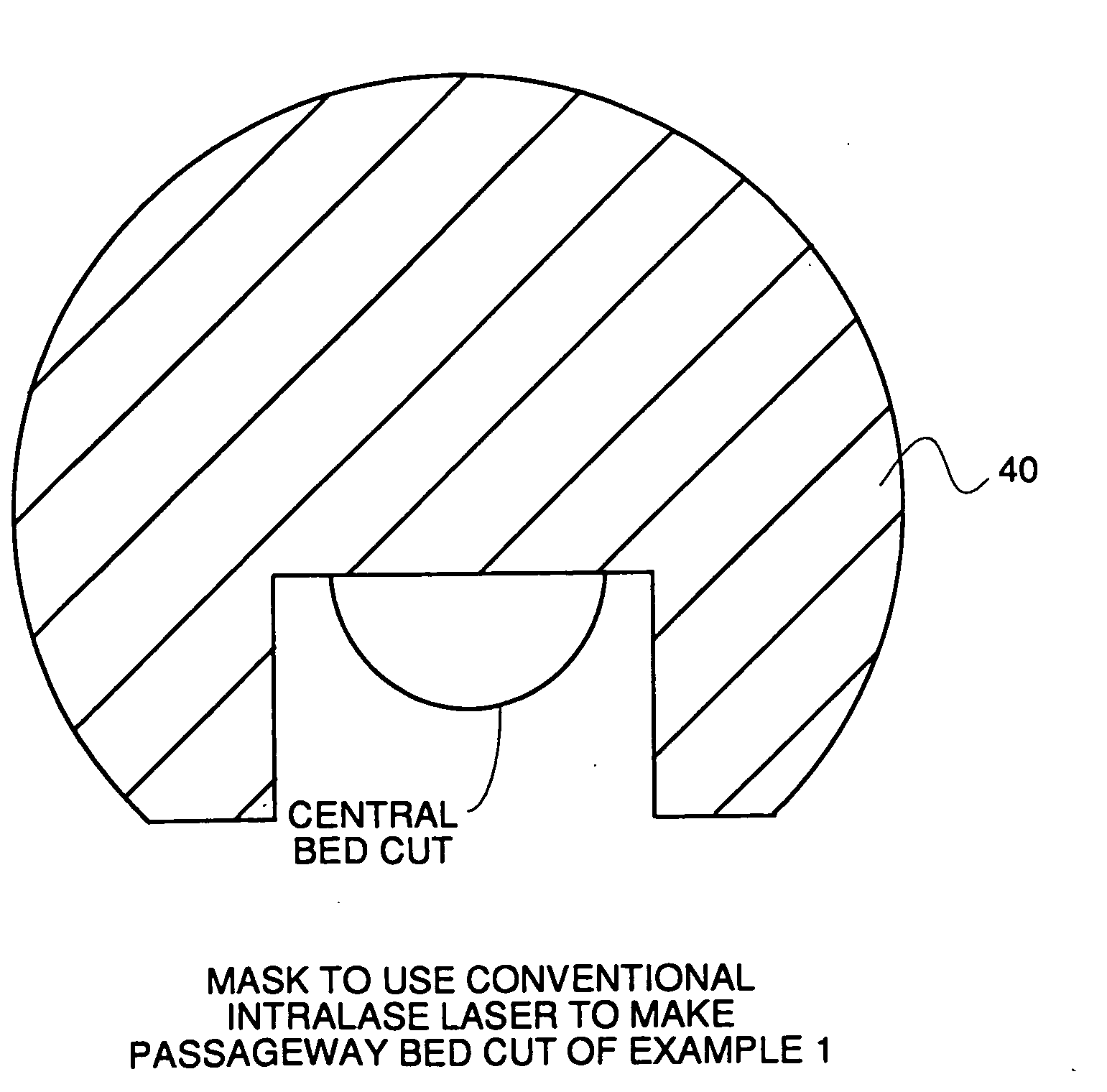
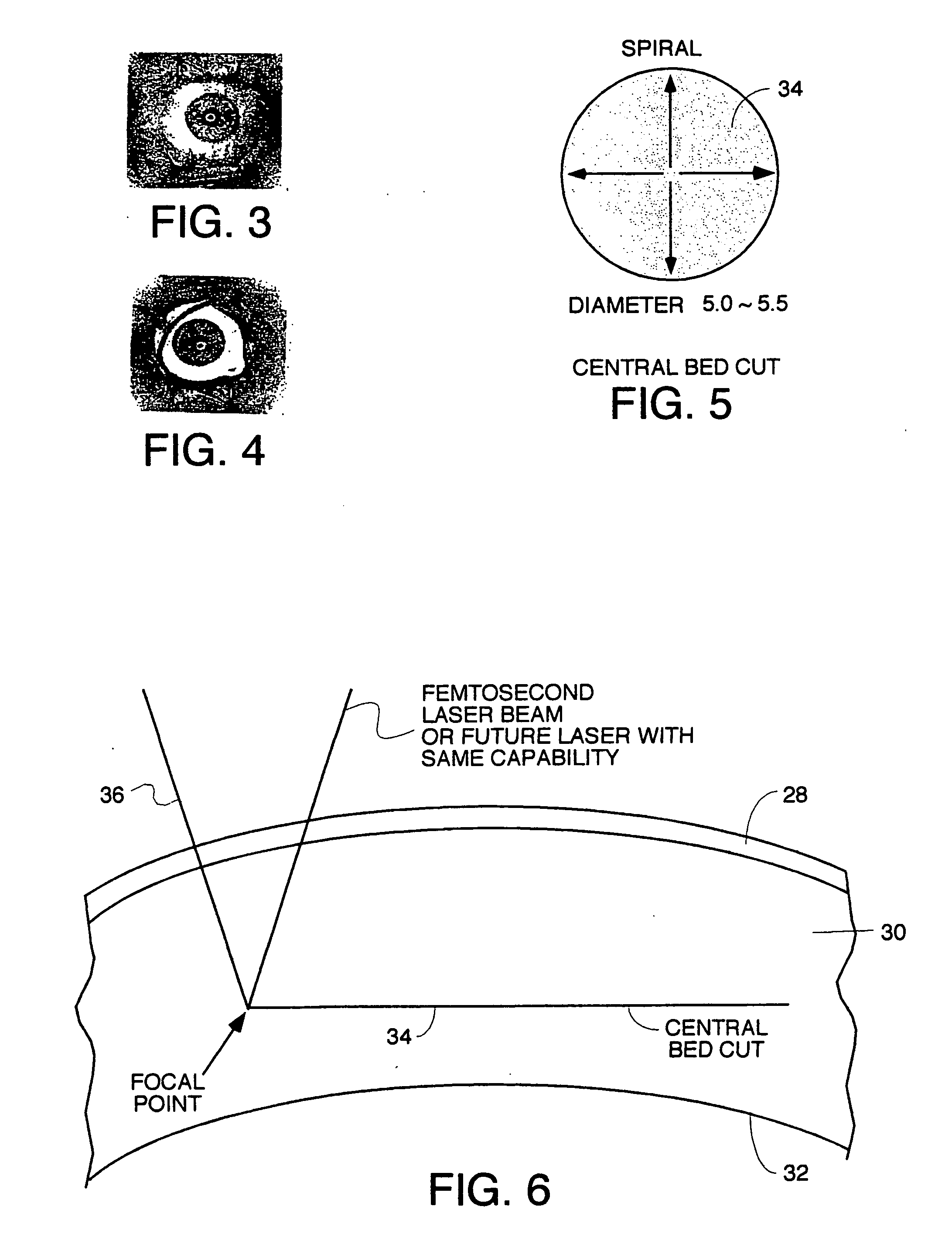
[0015]The function of the central bed cut is to provide a mechanical mounting for the lens or strengthening material to hold it in place. In the preferred example, the lens or strengthening material is a double network hyrdrogel with high permeability to oxygen and glucose and with high strength and elasticity.
[0016]If the patient is being treated for refractive error, the lens will have a shape which corrects the refractive error. If the procedure is used to treat only Keratoconus or Corneal Ectasia, the implant need not have any refractive error correction properties but, it must have sufficient structural strength to reinforce the cornea and add to its structural integrity to combat bulging out of the cornea due to the intraocular pressure. If the procedure is

Problems solved by technology

The presence of these cuts to the surface of the cornea along the non-LAS

Method used


Image

  • Surgical procedure and instrumentation for intrastromal implants of lens or strengthening materials
  • Surgical procedure and instrumentation for intrastromal implants of lens or strengthening materials
  • Surgical procedure and instrumentation for intrastromal implants of lens or strengthening materials

Examples


Embodiment Construction

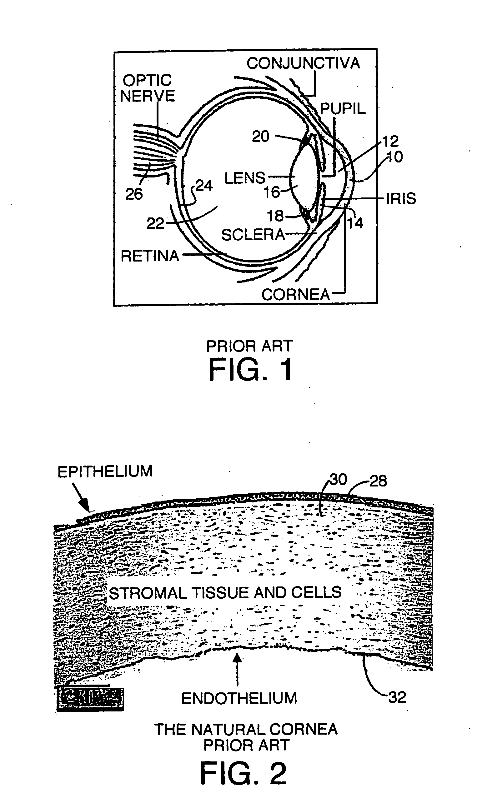
[0039]A schematic diagram of the human eye is shown in FIG. 1. The cornea 10 is the site where the surgical procedure will be performed. The cornea lies in front of the aqueous humor 12, the iris 14 which regulates the amount of light then enters the eye and the crystalline lens of the eye 16. The ciliary muscles that stretch the crystalline lens to change its shape are shown at 18 and 20. The vitreous humor 22 fills the eyeball and is a jelly-like substance which gives the eyeball its firmness. The retina is shown at 24 and lines the back of the eyeball. The retina is where the focused image is supposed to be if everything is perfect. The retina's rods and cones (not shown), sense the light pattern and send nervous signals to the brain on the optic nerve 26. The intraocular pressure exists in the area of the vitreous humor 12.

[0040]FIG. 2 is a diagram of the prior art natural cornea. The cornea is covered with a thin layer 28 called the epithelium. This layer is 4-5 cell layers thi...


PUM


Abstract

A surgical procedure for implanting a lens or strengthening material in a cornea without making a flap as is done in Lasik procedures. A femtosecond laser or some future developed laser which has the same ability is modified to cut a pocket in the stroma layer of a cornea with no side cuts and only an opening at the surface of a cornea. Alternatively, a modified microkeratome shaped and sized to form the desired shape for a passageway bed cut which is cut to join a central bed cut. Alternatively, the passageway bed cut can be done using a femtosecond laser or some future developed laser which has the same ability. The passageway bed cut is smaller in dimension than a central bed cut of a pocket in which the lens will be implanted in procedures where an expandable lens or strengthening material is used. A modified microkeratome having a web, a central blade shaped to form the passageway bed cut and sled runner on either side of the blade and separated therefrom is also disclosed. A patient interface with a mask is also disclosed to allow a femtosecond laser or some future developed laser which has the same ability may also be used to form both the central bed cut and a passageway bed cut or only a single bed cut with an opening at the surface of the cornea to form the pocket is also disclosed.

Description

BACKGROUND OF THE INVENTION[0001]The popularity of refractive surgery skyrocketed when surgical laser was introduced in 1980s. However, even the latest laser technology has its shortcomings. While laser is very effective in reducing the thickness of cornea with extremely high precisions in correcting refractive error, it has been useless against diseases caused by poor the structural integrity of cornea. Such diseases include Keratoconus and Corneal Ectasia. Keratoconus is insufficient corneal strength to withstand the intraocular pressure thereby causing bulging and thinning of the cornea. Corneal Ectasia is insufficient corneal strength to withstand the intraocular pressure causing bulging of the cornea and results from over thinning of the cornea during refractive surgery. This is a common complication of popular refractive surgeries. A surgical laser can never strengthen the cornea. It is therefore desirable that in any new surgical procedure to treat either Keratoconus or Corne...

Claims


Application Information

Patent Timeline
IPC IPC(8): A61B18/18
CPCA61F9/008A61F9/00827A61F2009/00872A61F9/009A61F9/00834
Inventor YAHAGI, TORU
Owner YAHAGI TORU
Why Eureka
Try Eureka