Digital filter and method for designing digital filters

Inactive Publication Date: 2007-09-20
LANTIQ BET GMBH & CO KG
View PDF10 Cites 3 Cited by
  • Summary
  • Abstract
  • Description
  • Claims
  • Application Information

AI Technical Summary

Benefits of technology

[0042] The invention also provides a polyphase filter arrangement with a number P of filter branches with in each case one inventive digital filter, with a switching device which couples a digital polyphase filter input signal into the filter branches in each case time delayed as branch signal, and with a summing device which combines the output signals of the filters to form a polyphase filter input signal. Such a polyphase filter arrangement has the advantage that the individual digital filters can be operated at a reduced clock rate. This is preferab

Problems solved by technology

When such integrator stages are connected in cascade in interpolation or in decimation filters, the bit width is in each case increased due to the integration process which necessitates disadvantageously wider memories for the delay elements.
In order to be able to use signal processing processors today in a flexible manner however, flexible adaptation of the filte

Method used


Image

  • Digital filter and method for designing digital filters
  • Digital filter and method for designing digital filters
  • Digital filter and method for designing digital filters

Examples


embodiment 400

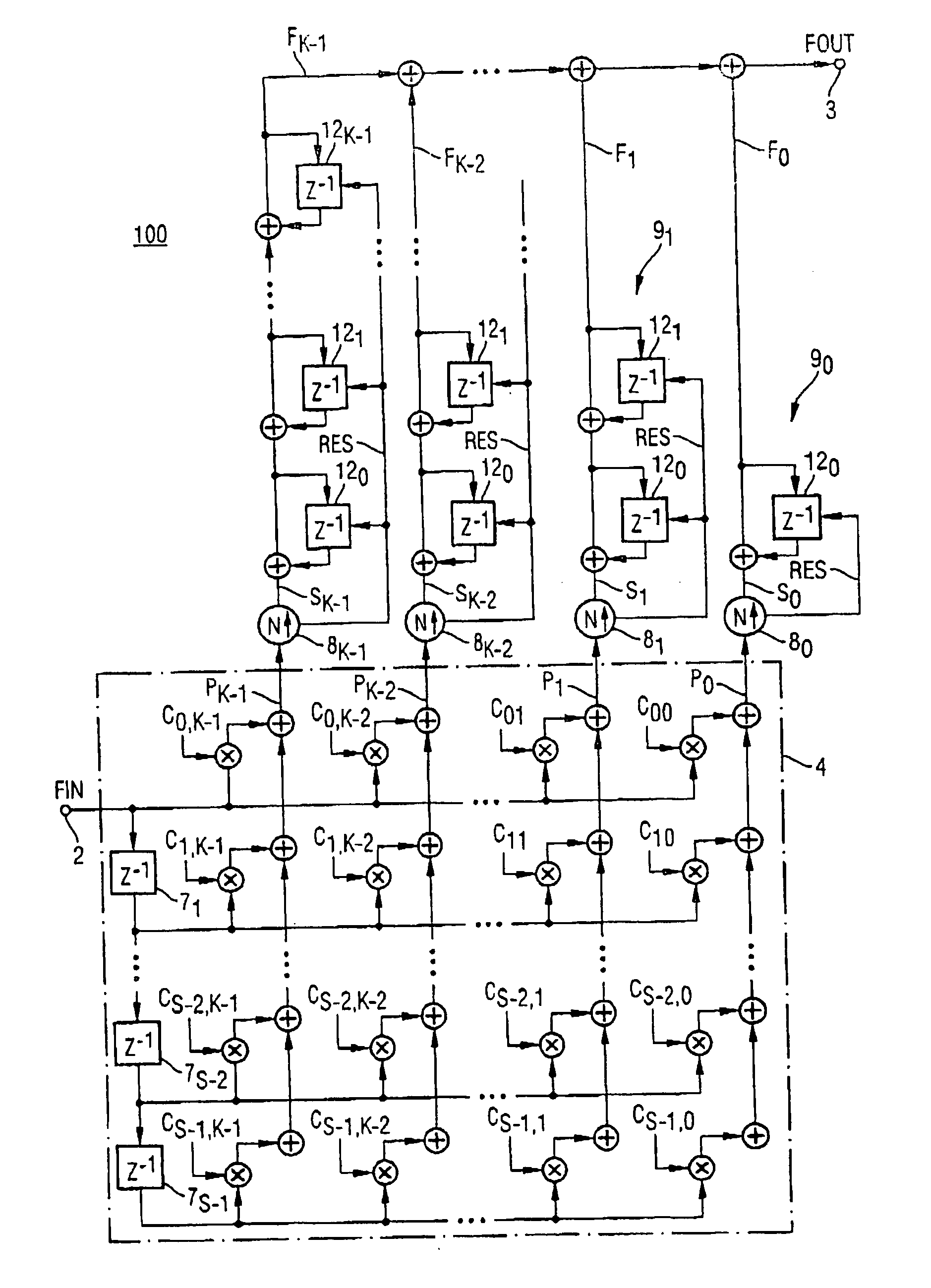
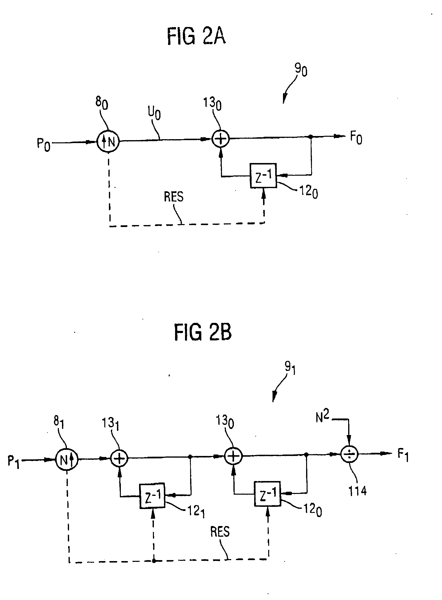
[0117] As an alternative, the delay elements 14j available in the integrator stage 15 can be arranged serially as a chain of delay elements with feedback. FIG. 5 shows a corresponding embodiment of the interpolation filter 300 according to the invention. The delay elements 14j are here in each case coupled back and interconnected in series between the output 3 of the filter and the kth gating device 8k, wherein the gating devices 8j are connected in each case at node 16 between the delay elements 14j with feedback. The respective interconnected delay elements 15j with feedback as integrators in this case have an impulse response proportional to H(z)=z−1 / (1−z−1). The chains of delay elements with feedback of the individual filter units 9j shown in FIGS. 2 and 3 can also be implemented in this form. FIG. 6 shows a corresponding alternative embodiment 400 of the filter units 9j.

[0118] According to the invention, analogously to FIG. 1, a decimation filter can also be constructed accordi...

embodiment 700

[0187]FIG. 20 shows a polyphase filter 930 arranged as interpolation filter. A common weighting network 4 is provided which has here a symmetric structure as is explained in greater detail in the embodiment 700 according to FIG. 15. At the input 2 of the polyphase filter 930, a chain 931 of series-interconnected delay elements is provided. The example shown here has P=4 polyphases. In this arrangement, a delayed internal signal can be supplied to each row of weighting coefficients Cij or, respectively, to the associated multipliers 6ij. In the example shown here, S / 2−1 rows are provided. Thus, 4 (S / 2−1)−2 delay elements are thus connected in series at the input 2 of the polyphase filter 930. The branch signals can be picked up in each case between the delay elements 931r.

[0188] The multiplications for calculating the linear combination of internal signals, now delayed, are in each case carried out with a delay of 1 / P of the baseband sampling period. The weighting network 4 is thus o...


PUM


Abstract

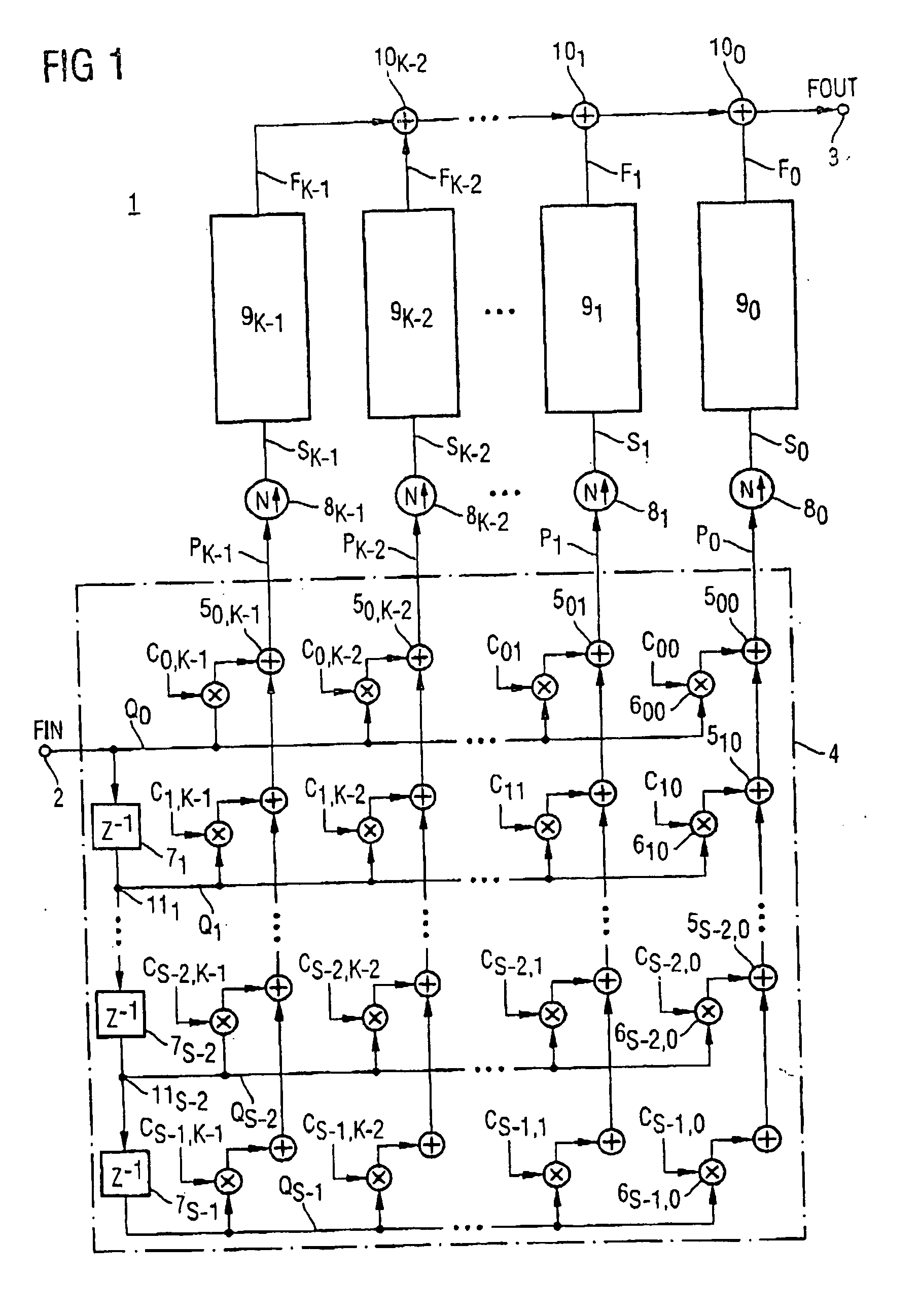
A digital filter comprises a plurality of filter units each realizing mutually independent filter functions with a predetermined recursive filter order on a signal path between the input and the output of the filter and operating at a first clock rate, a plurality of sampling devices operating at the first clock rate, and a weighting network coupled to the sampling devices and operating at a second clock rate. The filter units comprise at least one delay element which can be reset to a predeterminable value. To each of the filter units one of the sampling devices is allocated setting the respective delay element to a predetermined value dependent on a sampling rate conversion factor. An input signal is conducted, via the weighting network, to a respective sampling device, or digital internal sampling signals output by a respective sampling device are conducted to the output via the weighting network.

Description

BACKGROUND OF THE INVENTION [0001] The present invention relates to a digital filter, to a method for determining filter coefficients, and to a design method for constructing digital filters. [0002] In digital signal processing, signals must be frequently processed which have different clock frequencies on the signal processing path. For example, in DSL technologies, signals must be subjected to a sampling rate conversion in order to be forwarded from a clock domain which is operated at a baseband frequency to a further clock domain at a higher sampling frequency. Sampling rate conversions are effected by means of interpolation or decimation filters. An interpolation filter generates from a data stream with a lower sampling rate a data stream having a higher sampling rate, wherein intermediate values are determined from the input signal and are output as output bit stream with a high sampling rate. In this process, the signal is filtered in accordance with a filter function of the i...

Claims


Application Information

Patent Timeline
IPC IPC(8): G06F15/00
CPCH03H17/0277H03H17/0288H03H17/045H03H17/0444H03H17/0416
Inventor TRABER, MARIO
Owner LANTIQ BET GMBH & CO KG
Why Eureka
Try Eureka