
Process for manufacture of a latent heat storage device

a technology of latent heat storage and manufacturing process, which is applied in the direction of indirect heat exchangers, chemistry apparatus and processes, lighting and heating apparatus, etc., can solve the problems of increasing the difficulty of charging and discharging the latent heat storage device, the heat conductivity of most phase change materials is rather low, and the problem of increasing the difficulty of charging and discharging, etc., to achieve the effect of facilitating wetting of the expanded graphite material

Inactive Publication Date: 2007-09-27
SGL CARBON AG
View PDF17 Cites 22 Cited by
  • Summary
  • Abstract
  • Description
  • Claims
  • Application Information

AI Technical Summary

Benefits of technology

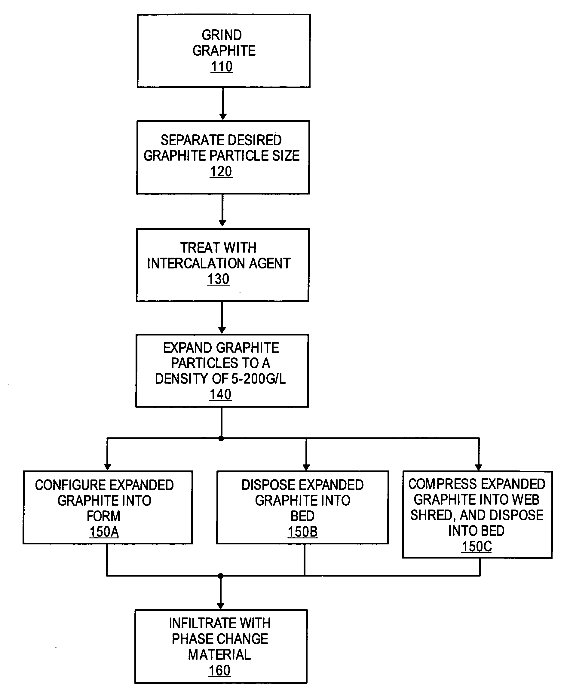
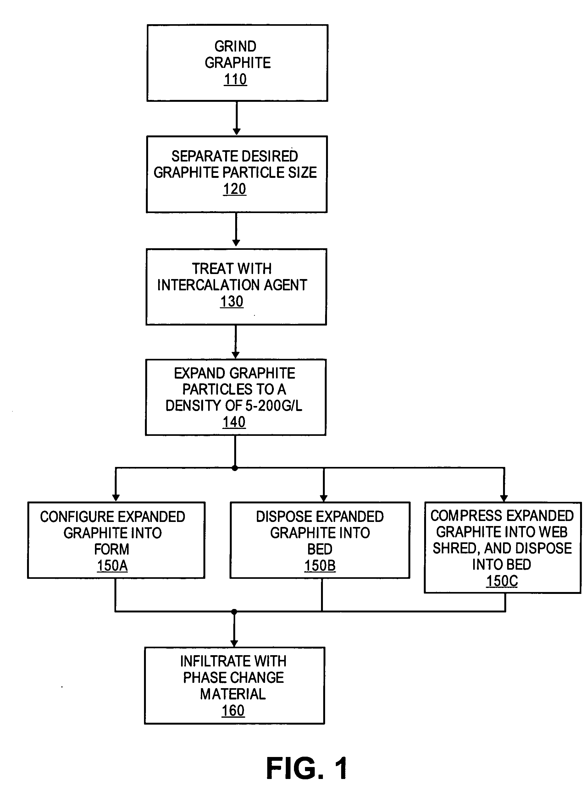
[0015]In one embodiment, the invention relates to a process for the preparation of a latent heat storage composite by infiltration of a phase change material into a matrix or packed bed of expanded graphite material wherein the interfacial energy between the expanded graphite material and the phase change material is reduced, resulting in a more readily wetting of the expanded graphite material by the phase change material. In another embodiment, of the invention, a process is provided for the manufacture of a latent heat storage device utilizing the latent heat storage composite prepared according to the invention.
[0016]In one embodiment, the degree of expansion of the graphite during the expansion process is controlled. More specifically, in one embodiment, the expansion process is controlled in such way that the bulk density of the expanded graphite material is not lower than 5 g / l and not higher than 200 g / l. It is believed that keeping the bulk density of the expanded graphite material within this range results in a less rugged surface of the expanded particles and a significant reduction of the amount of small pores, which are not readily infiltrated due to a negative capillary effect.
[0022]It should be noted that such means which reduce the degree of expansion of the graphite are contrary to the expansion procedures described, for example, in U.S. Pat. Nos. 3,404,061; 4,895,713; or 6,645,456. These and other prior art documents disclose expansion procedures which provide expanded graphite material suitable for the production of graphite foil. Throughout these prior art processes, a high degree of expansion is striven for because, typically, the more the graphite particles are expanded, the stronger the particles tend to interlock upon compression and as a result, stronger and tighter graphite foils can be produced. Thus, a high degree of expansion is generally a prerequisite for the production of graphite foil with a high mechanical strength and low fluid permeability, which can be used, for example, in the production of gaskets and seals.

Problems solved by technology

Unfortunately, the heat conductivity of most phase change materials is rather low.
As a consequence, the charging and discharging of a latent heat storage device is a relatively slow process.
There are several phase change materials, especially hydrophilic ones, which do not readily infiltrate into a porous matrix formed by compression of expanded graphite material because of a rather high interfacial energy between the phase change material and the graphite material of the matrix.
Due to a phenomenon known as negative capillary effect, this problem tends to be more severe the smaller the radii of the pores are.
The low PCM loading of a matrix with small pores results in a low energy density of the storage composite, and therefore a low efficiency.
Another drawback of the prior art is the need to carry out the infiltration under vacuum which makes the equipment for the infiltration rather complicated and expensive.
In contrast, preparation of an analogous composite by infiltration of the phase change material into a bed containing expanded graphite material as bulk good is rarely possible.
Due to the high interface energy between the expanded graphite material and the PCM, it is extremely difficult to infiltrate expanded graphite material as bulk good with a liquid PCM without foaming and floating of the expanded particles.

Method used


Image

  • Process for manufacture of a latent heat storage device
  • Process for manufacture of a latent heat storage device
  • Process for manufacture of a latent heat storage device

Examples


example 1

[0066]In order to determine the influence of the amount of the intercalation agent on the degree of expansion, a series of intercalation and expansion tests were performed. The mass of the starting graphite material (flakes of natural graphite) was the same in each test, but different amounts of intercalation agent were added to the graphite flakes.

[0067]Fumic nitric acid was used as the intercalation agent. The expansion was carried out at 500° C. In a second series of tests, the same amounts of fumic nitric acid were applied, but the expansion was carried out at 800° C.

[0068]The applied amount of natural graphite and acid, the expansion temperature and the density of the expanded graphite material are compiled in Table 1.

[0069]It can be seen that the density of the expanded graphite material tends to be higher the lower the amount of fumic nitric acid applied to a certain amount of natural graphite and the lower the expansion temperature. A higher density of the expanded graphite ...

example 2

[0070]In order to determine the influence of the expansion temperature on the degree of expansion, series of expansion tests at various temperatures were performed. For the expansion tests the sulfuric acid based intercalation compound Sumikon GHS SS3 low ash was used. The expansion was carried out at temperatures between 400° C. and 1000° C. The expansion temperature and the density of the expanded graphite material are compiled in Table 2.

[0071]Referring to Table 2, it can be seen that the density of the expanded graphite material tends to be higher the lower the expansion temperature is. A higher density of the expanded graphite material corresponds to a lower degree of expansion, and therefore to a less rugged and porous material, which is more easily infiltrated by a liquid phase change material.

TABLE 2Influence of the expansion temperature on the density of theexpanded graphite materialExpansionDensity of expandedtemperature / [° C.]graphite material / [g / l]400125008.56006.88004.9...

example 3

[0072]Different expanded graphite materials were prepared by carrying out the expansion at different temperatures. The first material was obtained by carrying out the expansion at 500° C. For sake of comparison, the other material was obtained by expansion at 800° C.

[0073]Each material was shaped into a plate-like porous matrix body (30×30×10 mm3) by application of moderate pressure. Both matrix bodies had a mass of about one gram / g, a density of about 0.1 g / cm3 and a porosity of 95%.

[0074]Each matrix body was infiltrated with a eutectic blend containing 58% by weight of KNO3 and 42% by weight of NaNO3. This phase change material melts at 220° C.

[0075]The infiltration was carried out in an autoclave. Prior to infiltration each matrix body was heated to 260° C. and covered by pouring the molten phase change material thereupon. The molten phase change material was also heated to 260° C. Infiltration was facilitated by at first evacuating the autoclave for 10 minutes and than applying ...


PUM

PropertyMeasurementUnit
Temperatureaaaaaaaaaa
Percent by massaaaaaaaaaa
Lengthaaaaaaaaaa

Abstract

A process for the preparation of latent heat storage composites is provided. The process comprises the steps of preparation of an expanded graphite material with a bulk density between 5 and 200 grams / liter which is readily wetted by a liquid phase change material, preparation of a pre-compressed matrix or a packed bed of the expanded graphite material, and manufacture of a latent heat storage composite by infiltration of the matrix or a packed bed with a phase change material in a liquid state.

Description

FIELD OF THE INVENTION[0001]The present invention relates to a process for the preparation of latent heat storage composites by infiltration of a phase change material into a matrix or a packed bed containing expanded graphite material, to a process for the manufacture of latent heat storage devices utilizing the latent heat storage composite prepared according to the invention, and processes for using the latent heat storage composites in latent heat storage devices.BACKGROUND OF THE INVENTION[0002]Phase change materials (PCM) are capable of storing heat energy in the form of latent heat. Such materials undergo a phase transition when heat is supplied or removed, e.g., a transition from the solid to the liquid phase (melting) or from the liquid to the solid phase (solidification) or a transition between a low-temperature and high-temperature modification or a hydrated and a de-hydrated modification or between different liquid modifications. If heat is supplied to or removed from a ...

Claims


Application Information

Patent Timeline
IPC IPC(8): B29C45/14
CPCC09K5/063F28D20/023F28F21/02Y02E60/145Y02E60/14
Inventor CHRIST, MARTIN U.OTTINGER, OSWIN H.BACHER, JURGEN J.HUDLER, BASTIAN
Owner SGL CARBON AG
Learn More