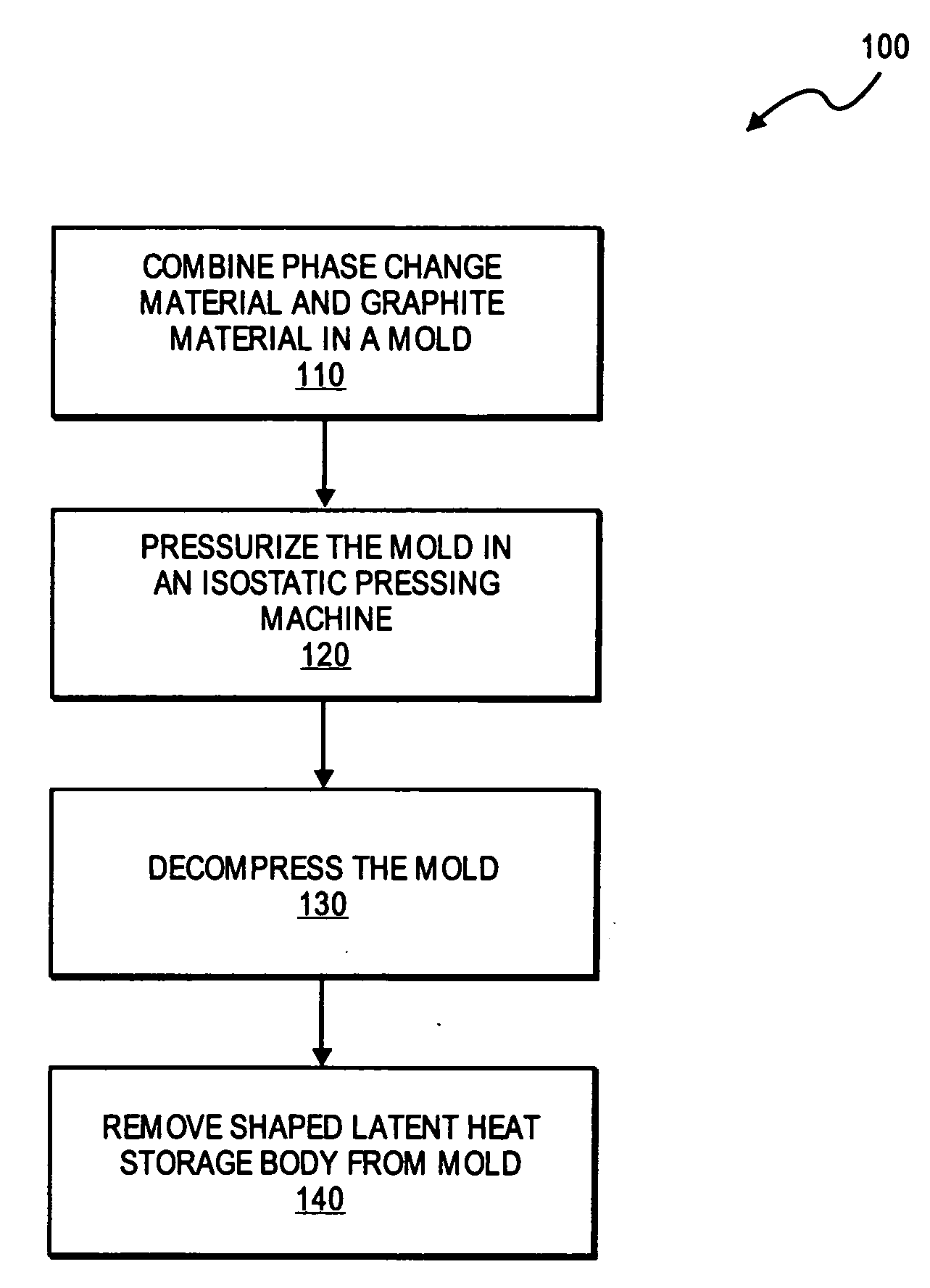
Process for manufacture of a latent heat storage body
a technology manufacturing process, which is applied in the direction of indirect heat exchangers, lighting and heating apparatus, transportation and packaging, etc., can solve the problems of increasing energy consumption, increasing the thermal conductivity of most phase change materials, and slow charging and discharging of latent heat storage devices, so as to reduce the thermal anisotropy of latent heat storage materials and reduce the design restrictions. , the effect of excellent edge quality
- Summary
- Abstract
- Description
- Claims
- Application Information
AI Technical Summary
Benefits of technology
Problems solved by technology
Method used
Image

Examples
example 1
[0037]A powder of the eutectic mixture of the salts potassium nitrate (KNO3) and (NaNO3) (80% by weight) and expanded graphite material (20% by weight) was prepared. The weight fractions of both, the eutectic salt mixture and expanded graphite material, are approximately equal to their volume fractions, because their densities are nearly equal (the density of the expanded graphite material is 2.20 g / cm3, and the density of the eutectic salt mixture is 2.18 g / cm3).
[0038]The expanded graphite material was obtained by compression of expanded graphite particles prepared by the expansion process described above into a planar foil-like web, and shredding the foil-like web into fragments resulting in particles. The mean particle size (d50 value) of the salt powder was about 1 mm, the mean particle size (d50 value) of the expanded graphite material was 0.5 mm. After dry mixing of the powders, the material was pressed uniaxially and isostatically, respectively.
[0039]For isostatic pressing, t...
example 2
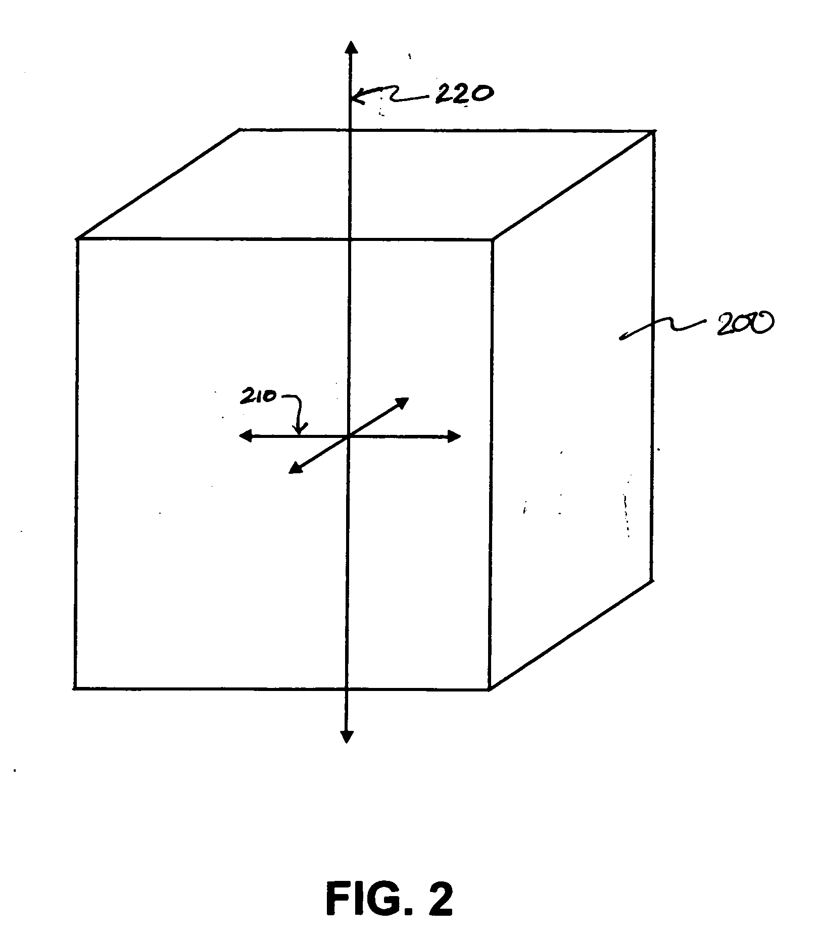
[0042]For comparison of the thermal conductivity of isostatically pressed bodies of a mixture of a phase change material and expanded graphite material and uniaxially pressed bodies of the same composition, block-shaped samples with comparable thermal in-plane conductivity were prepared by both manufacturing processes according to the procedure described in Example 1.
[0043]To determine the anisotropy, the thermal conductivity of both samples was measured in two directions, in-plane and through-plane. Within this context, in-plane means in horizontal direction of the mold during the filling process for the isostatically pressed sample, and perpendicular to the compressive force for the uniaxially compressed sample Through-plane designates the direction perpendicular to the in-plane direction. To characterize the anisotropy of the thermal conductivity, the anisotropy factor is calculated from the ratio of in-plane and through-plane thermal conductivity. Furthermore density and porosit...
PUM
 Abstract
Description
Claims
Application Information