
Magnetic recording medium and method of making the same

a recording medium and magnetic technology, applied in the field of magnetic recording mediums, can solve the problems of not providing sufficient flatness on the recording surface, not providing sufficient flatness on the recording layer, and foregoing methods that are not suitable for mass production of magnetic disks, etc., to achieve the effect of suppressing a nois

Active Publication Date: 2007-09-27
RESONAC CORP
View PDF6 Cites 15 Cited by
  • Summary
  • Abstract
  • Description
  • Claims
  • Application Information

AI Technical Summary

Benefits of technology

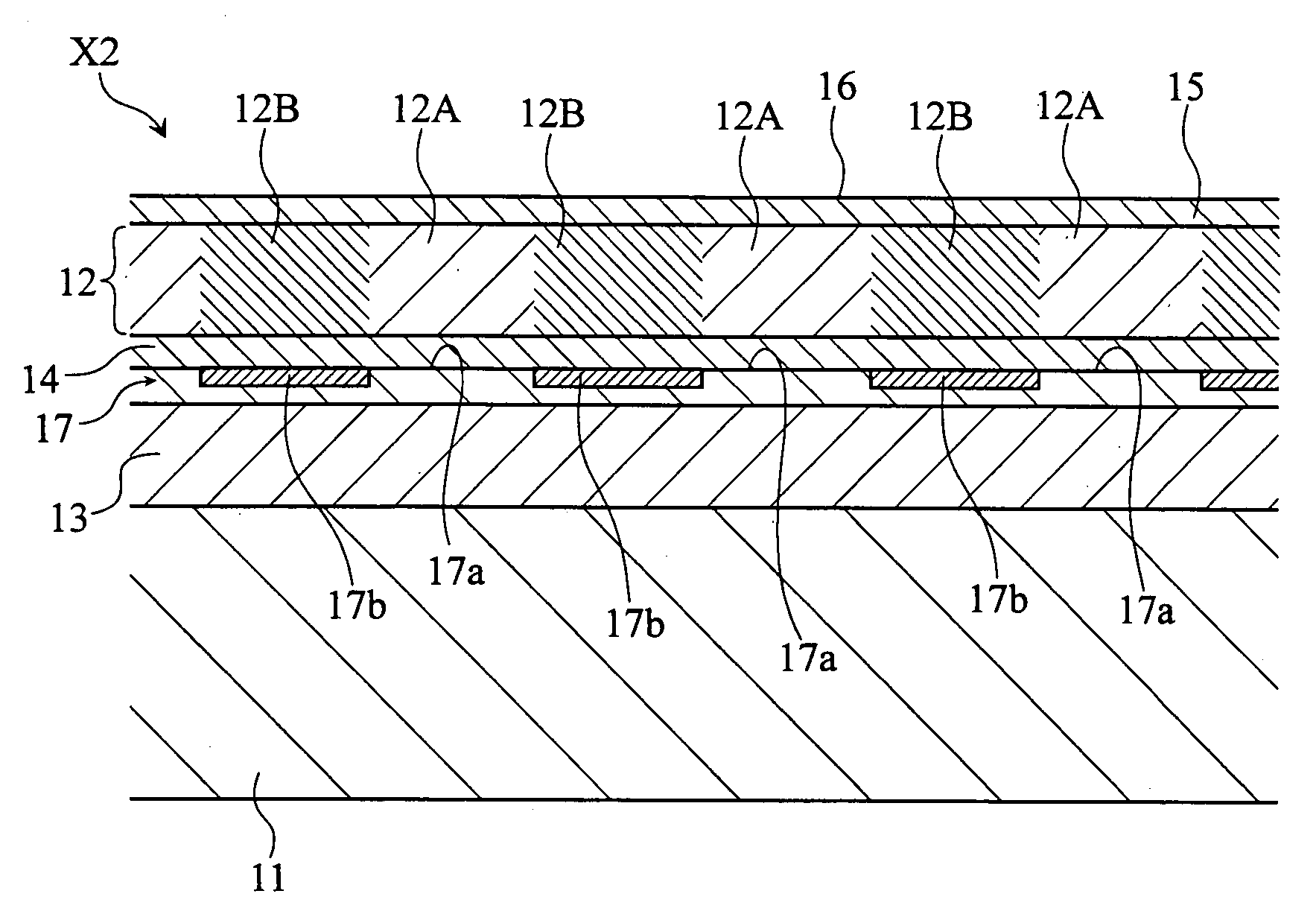
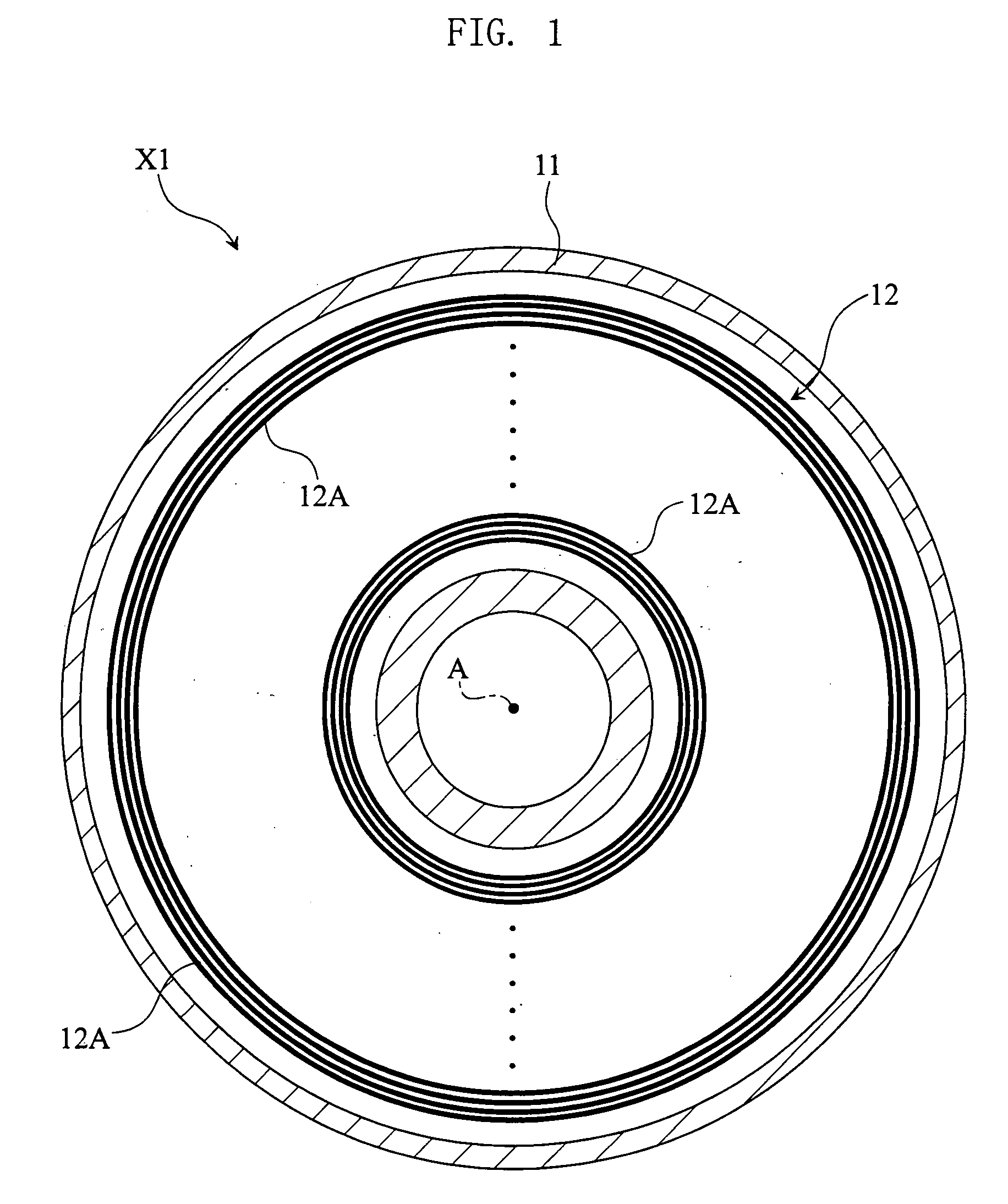
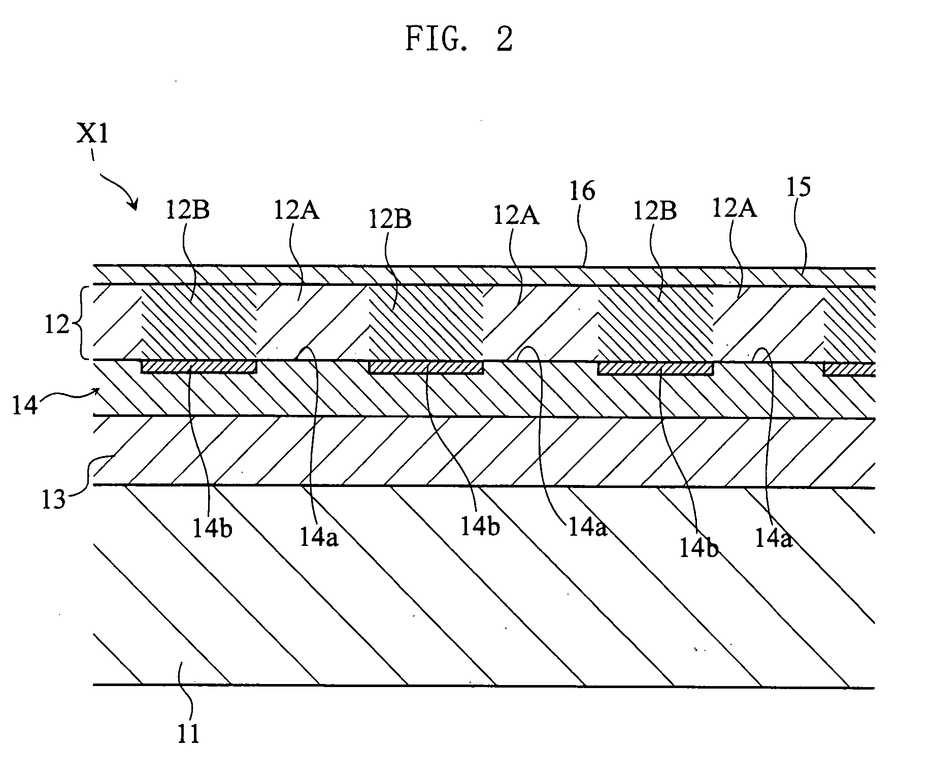
[0022]Through the seed layer formation step in the foregoing method, the seed layer can obtain on its surface the crystal plane or crystal structure that orients the magnetic easy axis of the magnetic film, constituted of the magnetic material for the recording layer, in a vertical direction. The pattern oxidation step allows oxidizing a partial region of a predetermined pattern on the seed layer (i.e. oxidizing the surface of the seed layer in a predetermined pattern), thereby forming an oxidized region of the predetermined pattern and a non-oxidized region of the predetermined pattern, on the seed layer surface. Then in the recording layer formation step, upon growing the magnetic material on the seed layer thus processed, the recording layer including the recording magnetic region and the non-recording magnetic region can be obtained. On the non-oxidized region on the seed layer surface during the recording layer formation step, the magnetic material epitaxially grows under a lattice matching with the crystal plane on the seed layer ground, so that the magnetic easy axis of the magnetic film is controlled to be vertically oriented, and thus the recording magnetic region having perpendicular magnetic anisotropy is obtained. In contrast, on the oxidized region on the seed layer surface during the recording layer formation step, the magnetic material inhibited from the lattice matching with the crystal plane on the seed layer ground by the oxidized coating randomly grows (non-epitaxial growth), so that a non-recording magnetic region in which a plurality of magnetic easy axes is randomly oriented (i.e. which does not have perpendicular magnetic anisotropy) is formed. Also, the foregoing method enables forming the recording layer which includes such recording magnetic region and non-recording magnetic region in a form of a continuous film structure, by a thin film formation technique such as a sputtering process. When forming the continuous film structure by a thin film formation technique, smaller surface unevenness i.e. higher surface flatness can be achieved than the non-continuous film structure as the recording layer 42 of the conventional magnetic disk 40. Accordingly, the proposed method is appropriate for attaining sufficient flatness on the recording surface that reflects the surface flatness of the recording layer. Thus, the magnetic recording medium manufacturing method according to the first aspect of the present invention is appropriate for fabricating a magnetic recording medium with a sufficiently flat recording surface, including a recording layer having a recording magnetic region of a predetermined pattern. The magnetic recording medium having the sufficiently flat recording surface is desirable in reducing the floating height of the magnetic head, and hence in increasing the recording density.
[0035]Preferably, the non-recording magnetic region according to the present invention may have longitudinal magnetic anisotropy. Such structure is desirable in restricting a reproduction signal detector or a reproduction magnetic head from detecting a magnetic flux originating from the non-recording magnetic region, when reproducing information by the magnetic recording medium based on perpendicular magnetic recording system according to the present invention, thereby suppressing a noise.

Problems solved by technology

Such process, however, does not provide sufficient flatness on the recording surface 44.
However as already stated, the conventional manufacturing method as described above does not provide sufficient flatness on the recording layer 42, and hence the recording surface 44.
Besides, the foregoing method is not suitable for mass production of the magnetic disk 40, from the viewpoint of production efficiency.
The foregoing method is, consequently, undesirable when executing mass production of the magnetic disk 40, because those series of steps cannot be arranged in a successive line.
These are additional disadvantages in adopting the foregoing method for mass production of the magnetic disk 40.

Method used


Image

  • Magnetic recording medium and method of making the same
  • Magnetic recording medium and method of making the same
  • Magnetic recording medium and method of making the same

Examples


working example 1

[0124]

[0125]A layered structure as that shown in FIG. 16 was prepared as a layered structure sample for the working example 1. To make up the layered structure sample, firstly a sputtering process was performed to deposit CoZrNb of a predetermined composition ratio on a glass substrate, thus forming a CoZrNb layer in a thickness of 100 nm. The CoZrNb is popularly employed to constitute the soft magnetic layer of the magnetic disk. The sputtering process was performed in a predetermined chamber, utilizing a predetermined sputtering apparatus. This also applies to the subsequent sputtering processes. The gas pressure in the chamber was set at 0.8 Pa.

[0126]Then Ru was deposited by sputtering, thus to form a Ru layer of 50 nm in thickness, on the CoZrNb layer. The Ru is popularly employed to constitute the seed layer of the magnetic disk. For this sputtering process, the gas pressure in the chamber was set at 0.6 Pa.

[0127]Again the sputtering process was performed to deposit Co77Cr20Pt3...

working example 2

[0130]A layered structure as that shown in FIG. 16 was prepared as a layered structure sample for the working example 2. To make up the layered structure sample, firstly a CoZrNb layer of 100 nm in thickness and a Ru layer of 50 nm in thickness were sequentially formed on a glass substrate, through similar methods to those employed in the working example 1. Oxygen was introduced into the chamber and increased the pressure in the chamber to 0.2 Pa, and the Ru layer was exposed to oxygen for one second. Then oxygen was substantially removed from the chamber and set the degree of vacuum at 1×10⁻⁶ Pa, after which the sputtering process was performed to deposit Co77Cr20Pt3—SiO2 on the Ru layer thus forming a CoCrPt—SiO2 layer of 15 nm in thickness. That is how the layered structure sample for this working example was prepared. With respect to the layered structure sample for this working example, the vertical coercivity and in-plane coercivity of the CoCrPt—SiO2 layer were measured simil...

working examples 3 to 7

[0131]Layered structure samples for the working examples 3 to 7 were prepared similarly to that of the working example 1, except that the oxygen exposure time of the Ru layer was set at two seconds (working example 3), four seconds (working example 4), eight seconds (working example 5), 16 seconds (working example 6), and 30 seconds (working example 7), instead of one second. With respect to the layered structure samples for the respective working examples, the vertical coercivity and in-plane coercivity of the CoCrPt—SiO2 layer were measured similarly to the layered structure sample for the working example 1. The measurement result of the vertical coercivity from the working examples 3 to 7 is indicated by plots E3 to E7 in the graph of FIG. 17, and the measurement result of the in-plane coercivity from the working examples 3 to 7 is indicated by plots E3′ to E7′ in the graph of FIG. 18.

[0132]

[0133]From the graph of FIG. 17, it is understood that because of the oxygen exposure of t...


PUM

PropertyMeasurementUnit
thicknessaaaaaaaaaa
widthaaaaaaaaaa
widthaaaaaaaaaa

Abstract

A magnetic recording medium includes a continuous recording layer, and a seed layer including a surface held in contact with the recording layer. The seed layer includes an oxidized region and a non-oxidized region in the surface held in contact with the recording layer. The recording layer includes a recording magnetic region and a non-recording magnetic region. The recording magnetic region corresponds in position to the non-oxidized region and has perpendicular magnetic anisotropy. The non-recording magnetic region corresponds in position to the oxidized region.

Description

BACKGROUND OF THE INVENTION[0001]1. Field of the Invention[0002]The present invention relates to a magnetic recording medium whose recording layer includes a recording magnetic region of a predetermined pattern. The present invention also relates to a method of making such a magnetic recording medium.[0003]2. Description of the Related Art[0004]A magnetic disk (magnetic recording medium) is well known as one of recording media that constitute storage apparatus such as a hard disk. The magnetic disk has a multilayer structure including a disk substrate and a recording layer with a predetermined magnetic structure. The ongoing increase in amount of information to be processed by a computer system is creating greater demand for a higher recording density from the magnetic disk.[0005]When recording information on the magnetic disk, a magnetic head for recording is disposed close to a recording surface of the magnetic disk (so as to float thereabove), and the magnetic head applies to the...

Claims


Application Information

Patent Timeline
Patent Type & Authority Applications(United States)
IPC IPC(8): G11B5/66B05D5/12
CPCG11B5/65G11B5/855G11B5/732G11B5/667G11B5/7379G11B5/658
Inventor IIDA, KOICHIOZAKI, KAZUYUKI
Owner RESONAC CORP
Learn More