

Resin Paste for Die Bonding
- Summary
- Abstract
- Description
- Claims
- Application Information
AI Technical Summary
Benefits of technology
Problems solved by technology
Method used
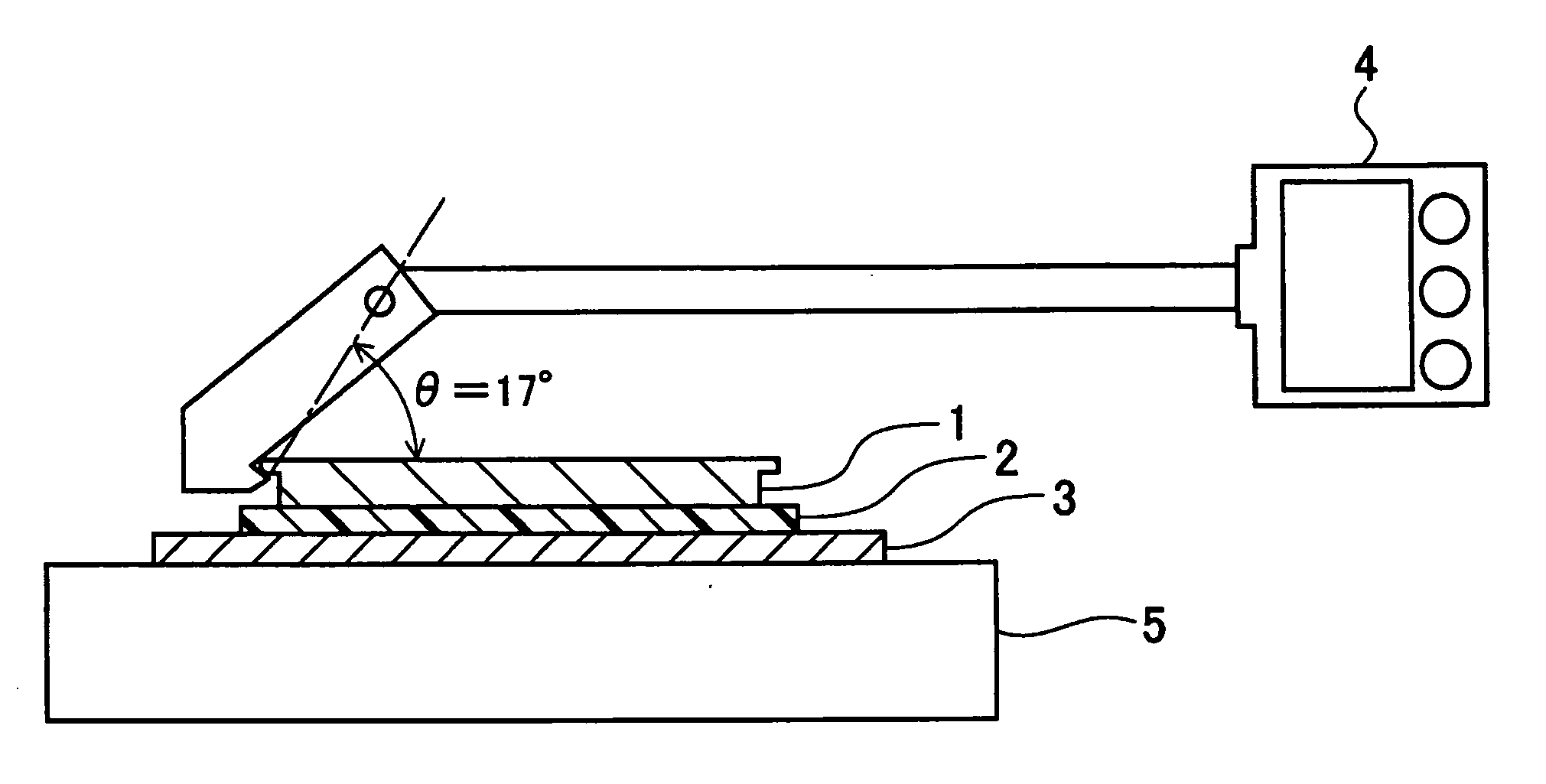
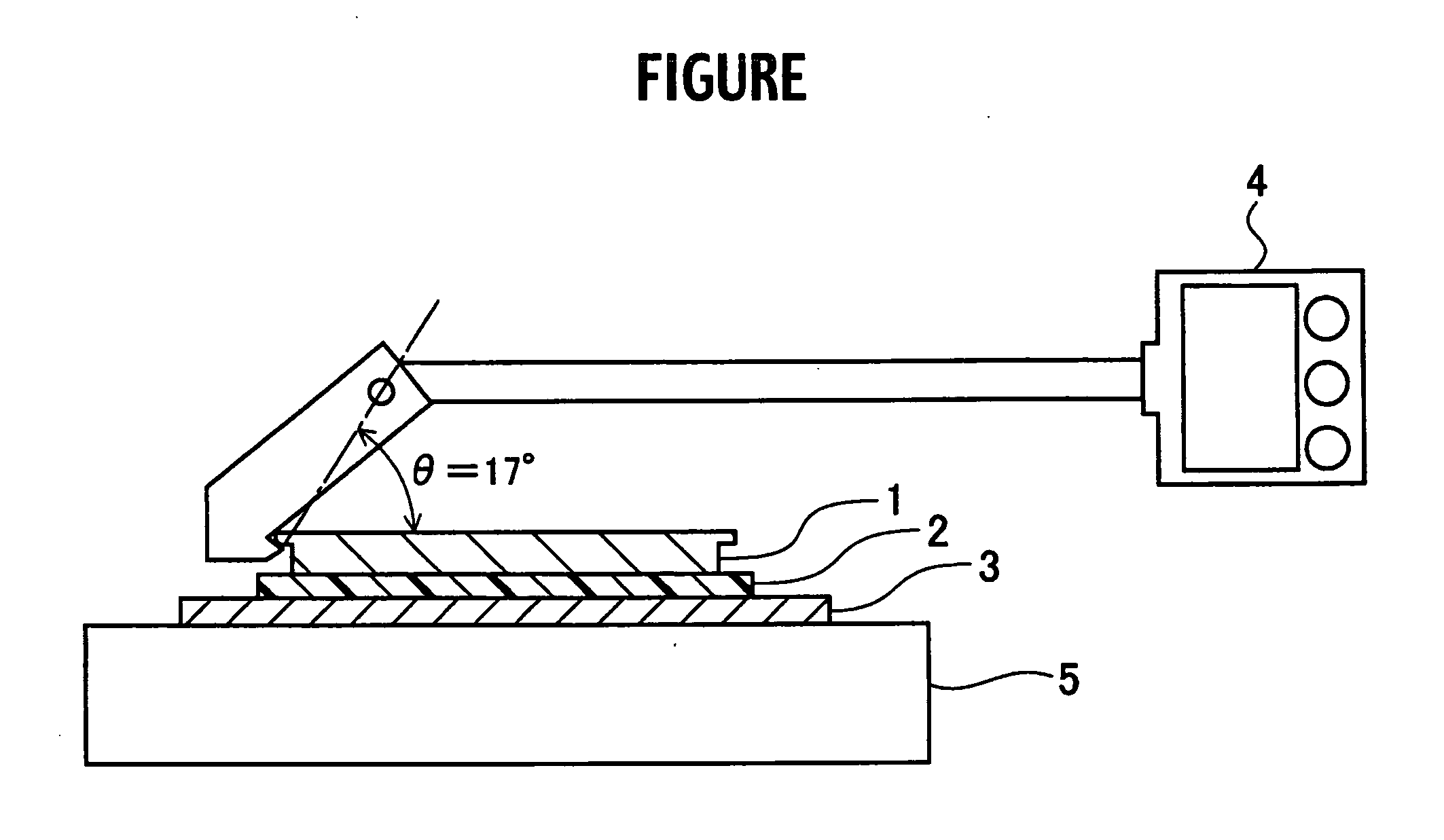
Image

Examples
example 1
[0076] 100 parts by weight of the powder of the polyimide resin PI1 obtained in the synthesis (1) was weighed and placed inside a stone mill, 150 parts by weight of carbitol acetate (CA) was added as a printing solvent, and the resulting mixture was stirred thoroughly using a three-roll mill to completely dissolve the resin (polyimide resin solid fraction concentration: 40% by weight). Subsequently, a previously prepared solution comprising 10 parts by weight of an epoxy resin (ESCN-195) and 5.3 parts by weight of a phenolic resin (H-1) dissolved in carbitol acetate (23 parts by weight), and an NMP solution comprising 0.2 parts by weight of a curing accelerator (2P4MHZ) (the solid fraction concentration of these thermosetting resins was approximately 40% by weight) were added to the solution and mixed, 17 parts by weight of a finely powdered silica Aerosil was added, and the resulting mixture was stirred and kneaded for 1 hour,. yielding a resin paste for die bonding according to th...
examples 2 to 10
, Comparative Examples 1 to 3
[0077] The nature and blend quantity of the polyimide resin, thermosetting resin, filler and / or solvent were altered, and preparation was conducted in the same manner as the example 1, yielding a series of resin pastes for die bonding according to the present invention (resin pastes No. 2 through No. 10) and a series of comparative resin pastes (No. 11 through 13). The composition of these resin pastes is shown in Table 1,
TABLE 1Example 1Example 2Example 3Example 4Example 5Example 6Example 7MaterialNo. 1No. 2No. 3No. 4No. 5No. 6No. 7Polyimide resinPI1PI1PI1PI2PI2PI2PI1100 100 100100 100 100 100 Epoxy resinESCN-195YDCH-702N865YDCH-702N865ESCN-195ESCN-195105010020152010Phenolic resinH-1H-1VH-4170VH-4170VH-4170H-1H-1 5.324 57 10.7 8.5 10.6 5.3Curing2P4MHZTPPKTPPKTPPK2P4MHZ2P4MHZTPPKaccelerator 0.2 0.5 1.0 0.2 0.3 0.4 0.2FillerAerosilAerosilAerosilAerosilAerosilAerosilAerosil1735 5126192017BN 5SolventCATGTGCATGTGTG173 262 387196 186 197 256 Comp...
PUM
| Property | Measurement | Unit |
|---|---|---|
| Temperature | aaaaa | aaaaa |
| Percent by mass | aaaaa | aaaaa |
| Percent by mass | aaaaa | aaaaa |
Abstract
Description
Claims
Application Information