
Microtome

a microtome and microtome technology, applied in the field of microtomes, can solve the problems of complex mechanism, unusable sectioning waste, unavoidable fine sectioning waste, etc., and achieve the effects of low water uptake, high dimensional accuracy, and good impact toughness

Active Publication Date: 2007-10-04
LEICA BIOSYST NUSSLOCH
View PDF28 Cites 21 Cited by
  • Summary
  • Abstract
  • Description
  • Claims
  • Application Information

AI Technical Summary

Benefits of technology

[0012]What has been recognized according to the present invention is firstly that thin sections of contaminated samples, especially those dropping down, adhere very particularly firmly to housing portions of the microtome, and in particular to the section collection pan, if the housing portions of the microtome and / or the section collection pan are electrostatically charged. It is therefore proposed, in accordance with the present invention, that the components of the microtome that usually come into contact with paraffin sections and / or with sectioning waste be embodied in electrically conductive fashion. Ideally, therefore, all components that come into contact with paraffin sections and / or with sectioning waste are embodied in electrically conductive fashion. It could also be sufficient, however, to embody in electrically conductive fashion substantially and only the components of the microtome that most probably or most frequently come into contact with paraffin sections and / or with sectioning waste. By the fact that the relevant components are embodied in electrically conductive fashion, they should all be at a common electrical potential, and electrostatic charging of individual components of the microtome should accordingly be effectively avoided. It is thereby possible to decrease the possibility that, in particular, thin sections, paraffin sections, and / or sectioning waste becomes permanently or particularly firmly deposited onto individual components of the microtome because of electrostatic charging of the individual components, and can be removed again with difficulty or only with time-consuming cleaning efforts.
[0016]Very particularly preferably, at least one housing portion could comprise a plastic having the designation “Grilon BS EC.” This plastic is a standard-viscosity, more heat-stabilized injection-molding PA6 grade having stainless steel fibers, this plastic exhibiting electrical conductivity or electrical antistatic properties in particular because of the stainless steel fibers. This plastic moreover exhibits thermoplastic properties with good impact toughness, and can be made light in color. This plastic is offered commercially, for example, by EMS Grivory or EMS-CHEMIE GmbH, Warthweg 14, 64823 Gross-Umstadt, Germany. Alternatively or additionally, at least one housing portion could be a plastic having the designation Antistatic-Equipped “Grilamid LKN-5H,” of the same manufacturing company. Grilamid LKN-5H is a heat-stabilized polyamide-12 reinforced with 50% glass spheres. The properties of this injection-molding grade are: low water uptake, extremely dimensionally accurate, dimensionally stable, very little shrinkage, good sliding properties, and high abrasion strength.

Problems solved by technology

Unusable sectioning waste occurs in this operation, and accumulates in a section collection pan of the microtome.
The samples to be investigated are often contaminated or bacterially infected biological material with which paraffin from the preparation process can be mixed.
Even during ordinary sectioning of the samples with the microtome, fine sectioning waste unavoidably occurs; this drops down from the microtome knife and becomes deposited on portions of the microtome located therebelow, for example portions of its housing, in particular also in open gaps and especially in the section collection pan.
Because of the very complicated motion sequence, a complex mechanism is necessary on and in the microtome.
Openings into the interior of the microtome, which are often covered with movable sliders, unavoidably remain at movement interfaces.
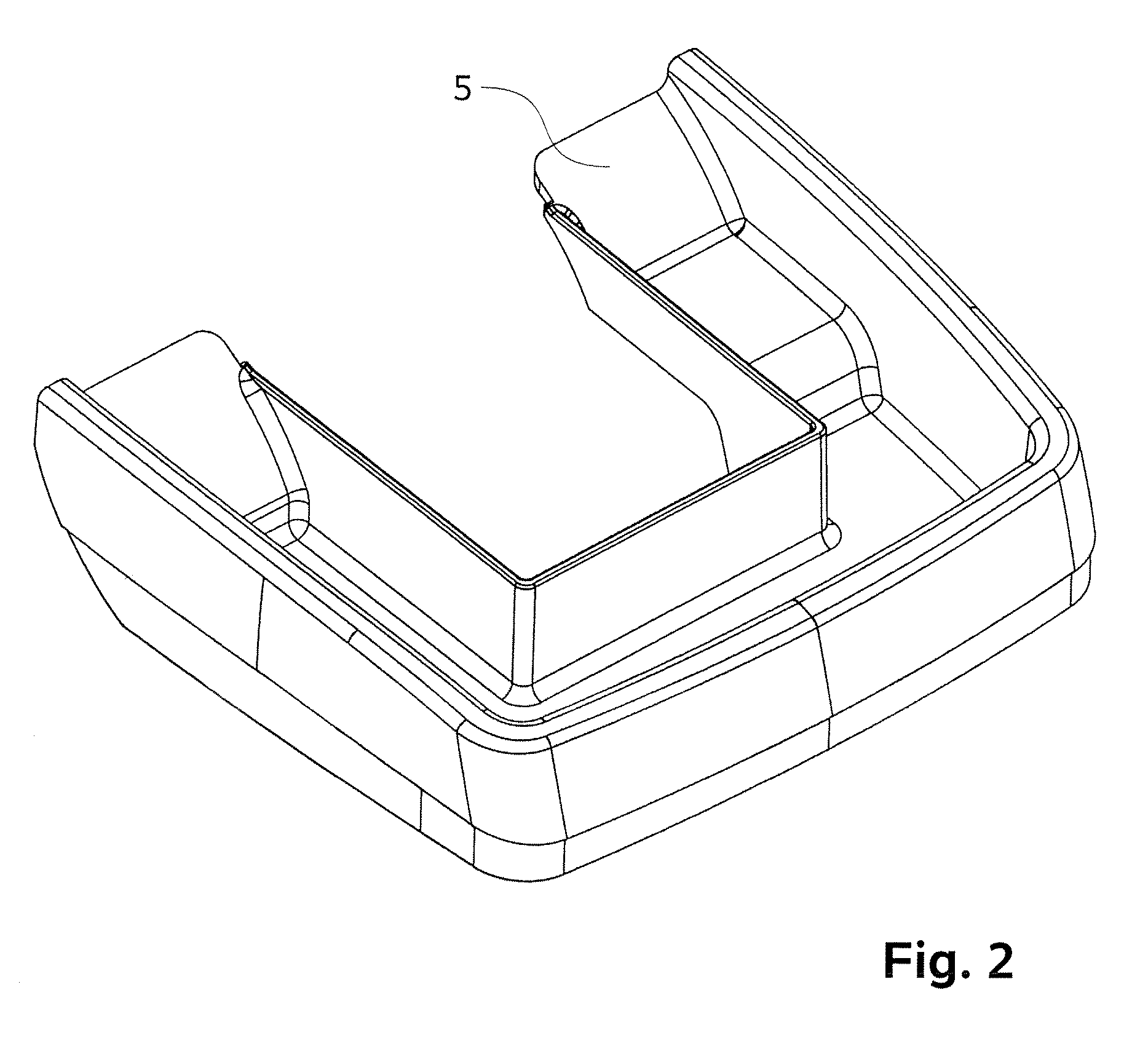
The section collection pan is particularly affected, since both the sectioning waste from trimming sections and the thin sections of contaminated samples that drop down build up in it.
Large adhering sectioning waste fragments that are firmly in contact with the surface because of adhesion present a particular cleaning problem.

Method used


Image

  • Microtome
  • Microtome
  • Microtome

Examples


Embodiment Construction

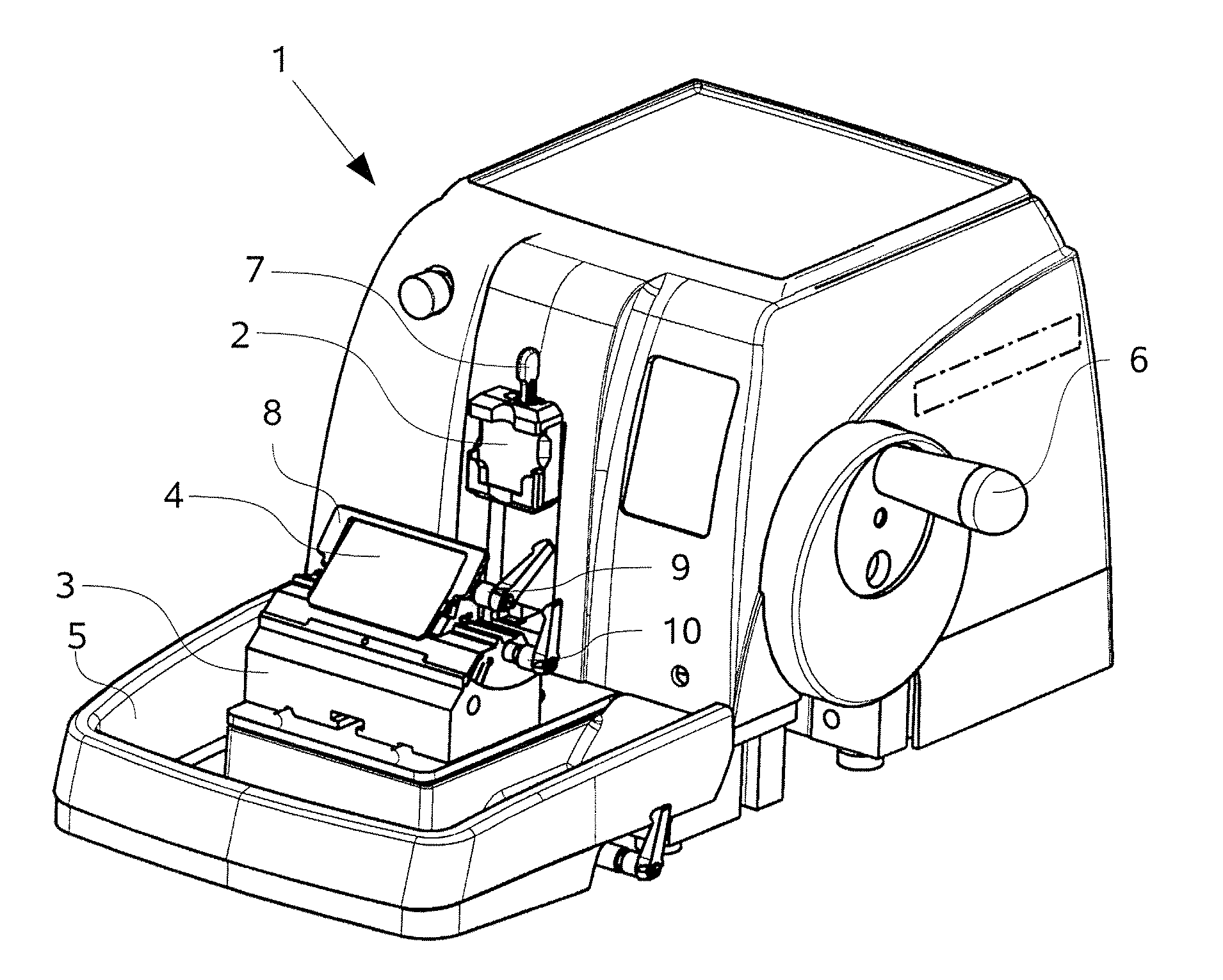
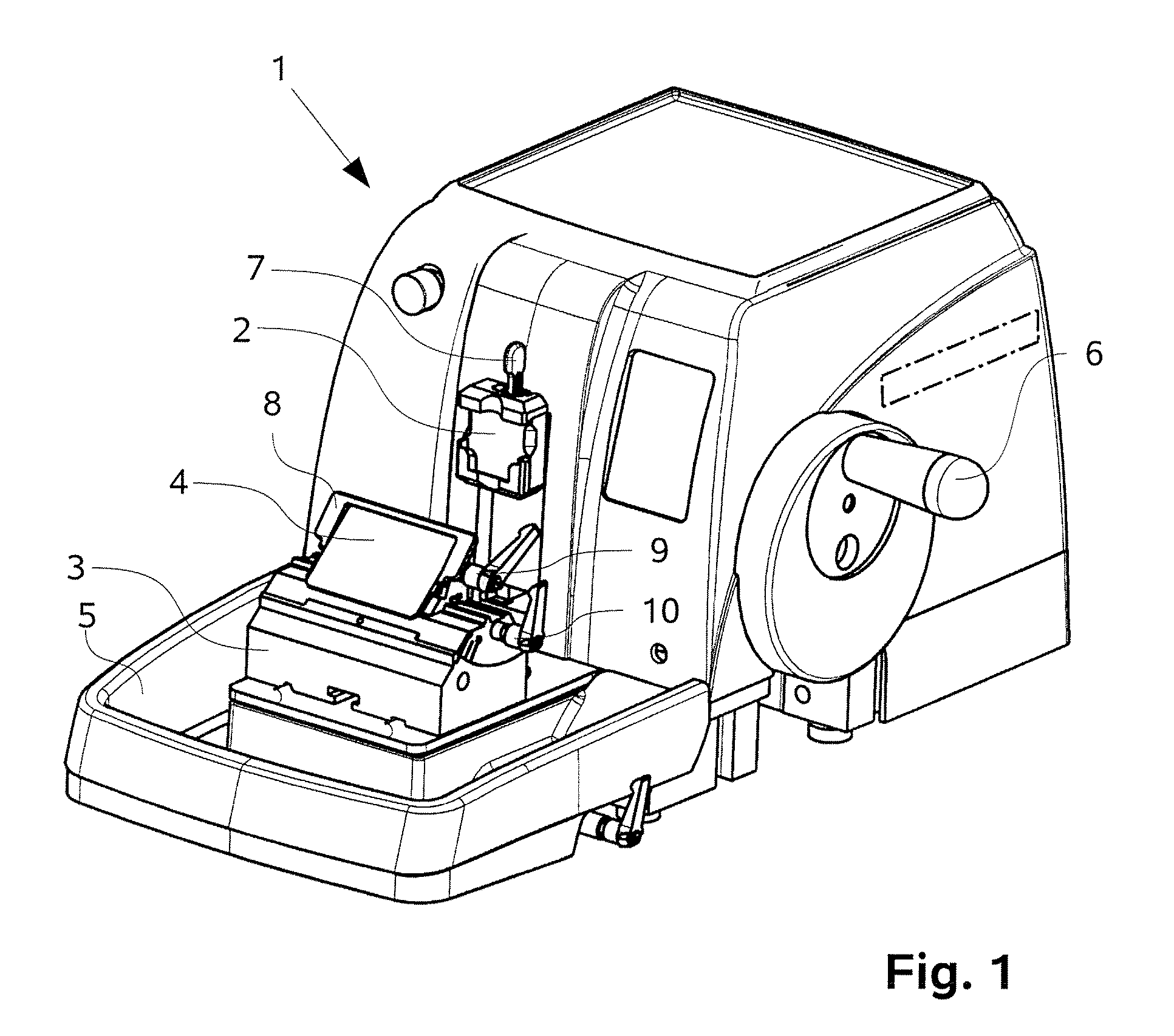
[0024]FIG. 1 shows a rotary microtome 1 having functional regions to be operated manually, namely sample holder 2, cutting device 3, and section removal system 4. The sectioned material (not shown) dropping down from section removal system 4 is accumulated in a section collection pan 5. The up-and-down motion of sample holder 2, and the shifting of cutting device 3, are controlled by actuation of a hand crank 6 via a linkage (not further depicted).

[0025]The functional units are constructed from a plurality of structural elements. A clamping lever 7 is provided for rapid exchange of a sample carrier (not shown). Microtome knife 8 can also be aligned and immobilized in a pivotable knife receptacle by way of clamping shafts 9, 10. Cutting device 3 is mounted on concealed guidance rails.

[0026]Poorly accessible cavities and narrow slits and gaps, in which contaminated sectioned material can become deposited, are created for structural reasons when the numerous structural elements are fit...


PUM

PropertyMeasurementUnit
Electrical conductivityaaaaaaaaaa
Metallic bondaaaaaaaaaa

Abstract

The present invention relates to a microtome (1) having functional regions to be operated manually, in particular a sample holder (2), a cutting device (3), a section removal system (4), and a section collection pan (5). A microtome (1) is described in which the particularly firm contact or adhesion of sectioning waste fragments and, in particular, of thin sections can be at least largely avoided. For this purpose, the microtome (1) according to the present invention is characterized in that the components of the microtome (1) that can be brought into contact with paraffin sections are embodied in electrically conductive fashion.

Description

CROSS REFERENCE TO RELATED APPLICATIONS[0001]This application claims priority of German utility model application 20 2006 005 259.3 filed Mar. 30, 2006 and German utility model application 20 2006 008 329.4 filed May 26, 2006, which are both incorporated by reference herein.FIELD OF THE INVENTION[0002]The present invention relates to a microtome having functional regions to be operated manually, in particular a sample holder, a cutting device, a section removal system, and a section collection pan.BACKGROUND OF THE INVENTION[0003]Microtomes of this kind are known from the existing art, for example from DE 103 52 578 B3, and are used predominantly for the production of thin paraffin sections in the fields of biology, medicine, and industrial research. The samples and preparations to be investigated are usually embedded in paraffin, in a preceding preparation process, into a specimen holding device, for example a carrier basket. A drive device that, by means of a relative motion, guid...

Claims


Application Information

Patent Timeline
IPC IPC(8): B26D7/06
CPCG01N1/06Y10T83/202Y10T83/6508Y10T83/6492
Inventor KUNKEL, STEFANSAUER, FRANKSCHNEIDER, VOLKER
Owner LEICA BIOSYST NUSSLOCH
Learn More