Internal combustion engine having improved fuel pump configuration, and vehicle including same

a technology of internal combustion engine and fuel pump, which is applied in the direction of fuel injecting pump, machine/engine, valve drive, etc., can solve the problems of increasing the the pipe connection between the fuel pump and the carburetor is relatively long, and the percolation may arise in the fuel pump, so as to reduce the overall weight of the internal combustion engine, reduce the number of components, and improve endurance performan

Inactive Publication Date: 2007-10-04
HONDA MOTOR CO LTD
View PDF19 Cites 40 Cited by
  • Summary
  • Abstract
  • Description
  • Claims
  • Application Information

AI Technical Summary

Benefits of technology

[0021]In addition, in the case where the cam drive mechanism is contained in the inside of the endless power transmission belt chamber, the cam drive mechanism includes the cam endless power transmission body, and the pump drive mechanism includes the pump sprocket driven by the cam endless power transmission body, a rotating member already provided in the internal combustion engine can be utilized as a drive element of the pump drive mechanism, which makes it possible to reduce the number of component parts for exclusive use in the pump drive mechanism, and to reduce the overall weight of the internal combustion engine. The rotating speed of the crankshaft varies according to the operating condition of the internal combustion engine, and the variations in rotation are exerted also on the endless power transmission body. Thus, the endless power transmission body must have endurance performance for stably operating against the variations in rotation. In the present configuration, the variations in rotation of the endless power transmission belt are attenuated, by using drive friction of the fuel pump, whereby enhanced endurance performance of the endless power transmission belt is obtained.
[0022]In addition, in the case where the cam is provided on the web of the crankshaft and the pump drive mechanism includes the rod abutting on the cam, also, the pump drive mechanism can be configured by utilizing a rotating member already provided in the internal combustion engine, so that the number of component parts for exclusive use in the pump drive mechanism are reduced, and the overall weight of the internal combustion engine is also reduced.
[0023]In addition, in the case where the pump drive sprocket rotates as one body with the primary speed reduction driven element of the power transmission device, a driving force with speed reduction relative to the crankshaft can be transmitted, the fuel pump can thereby be driven at a lower rotating speed, and, therefore, a reduction in the pump drive loss is obtained. In addition, since the pump mechanism is so configured as to pick up power with speed reduction, it is unnecessary to attain a large speed reduction in the pump drive mechanism, so that it is possible to reduce the diameter of the pump drive sprocket and to reduce the area occupied by the pump endless power transmission belt.
[0024]Further, in the fuel pump for an internal combustion engine in another aspect of the invention, the fuel pump is provided at a position spaced from the exhaust pipe and near the fuel injector, so that a more simple heat insulation structure for the fuel pump can be used, and a reduction in the pump drive loss is obtained. Furthermore, the cylinder block is mounted on the vehicle with the axis of the cylinder chamber inclined toward the front side, the cylinder block and the cylinder head are provided to be exposed from the frame, and the fuel pump is provided on the upper side (the front side, in the forwardly inclined posture) of the cylinder head. Therefore, the fuel pump is air-cooled due to the collision of the running airflow on the fuel pump during running of the vehicle, whereby the operating performance of the fuel pump is enhanced.
[0025]In this instance, the pump drive mechanism is configured by providing the drive gear on the camshaft provided in the cylinder head, whereby the fuel pump is provided closer to the camshaft, as compared with the chain power transmission system. As a result, an increase in the vertical length (the front-rear length, in the forwardly inclined posture) of the internal combustion engine can be avoided. In addition, where the pump drive mechanism is of the chain power transmission system, the camshaft, the pump drive mechanism and the fuel pump must be mounted at the same time. In the present configuration, on the other hand, the fuel pump provided with the driven gear can be mounted after the camshaft provided with the drive gear is mounted, whereby ease of assembly is enhanced.
[0026]Furthermore, in the fuel pump for an internal combustion engine according to still another aspect of the present invention, also, the fuel pump is provided at a position spaced from the exhaust pipe and near the fuel injector, so that a more simple heat insulation structure for the fuel pump can be used, and a reduction in the pump drive loss is obtained. In addition, since the fuel pump is provided on the front side of the cylinder head and on the lower side of the intake gas routing pipe, the fuel pump is air-cooled during running of the vehicle, whereby the operating performance of the fuel pump can be enhanced.

Problems solved by technology

As a result of exposure to radiant heat generated by the exhaust pipe, problems such as percolation may arise in the fuel pump.
In addition, since the intake air routing assembly is connected to a rear portion of the cylinder head, the pipe connecting the fuel pump and the carburetor to each other is relatively long.
This leads to an increase in the weight of the internal combustion engine, and to a pressure loss during the process of supplying the fuel from the fuel pump to the carburetor, possibly resulting in a loss of drive of the fuel pump.
Therefore, the drive element of the cam drive mechanism must be disposed with an offset to the axially outer side by an amount corresponding to the space secured for forming the inside wall, resulting in the formation of a dead space on the axially inner side of the drive element of the cam drive mechanism, over the crankshaft.

Method used


Image

  • Internal combustion engine having improved fuel pump configuration, and vehicle including same
  • Internal combustion engine having improved fuel pump configuration, and vehicle including same
  • Internal combustion engine having improved fuel pump configuration, and vehicle including same

Examples


first embodiment

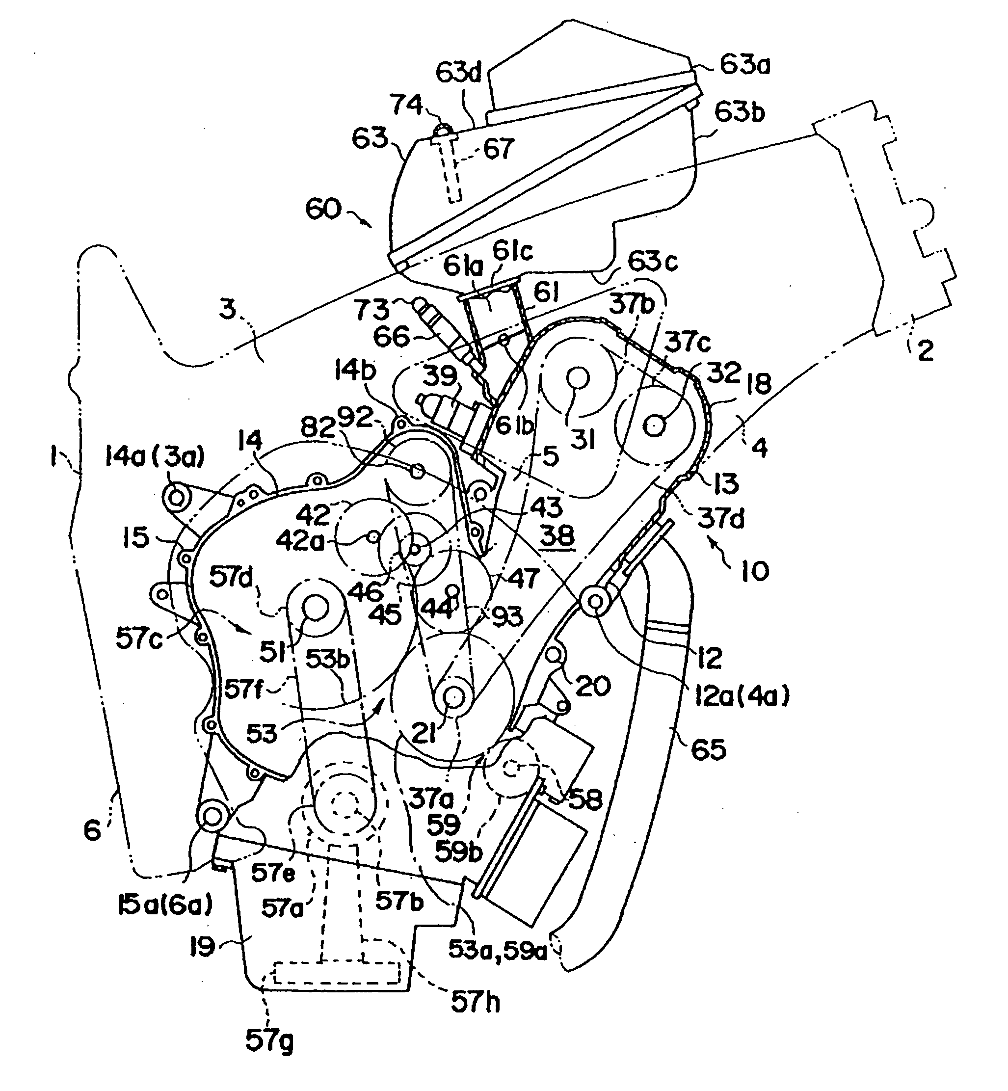
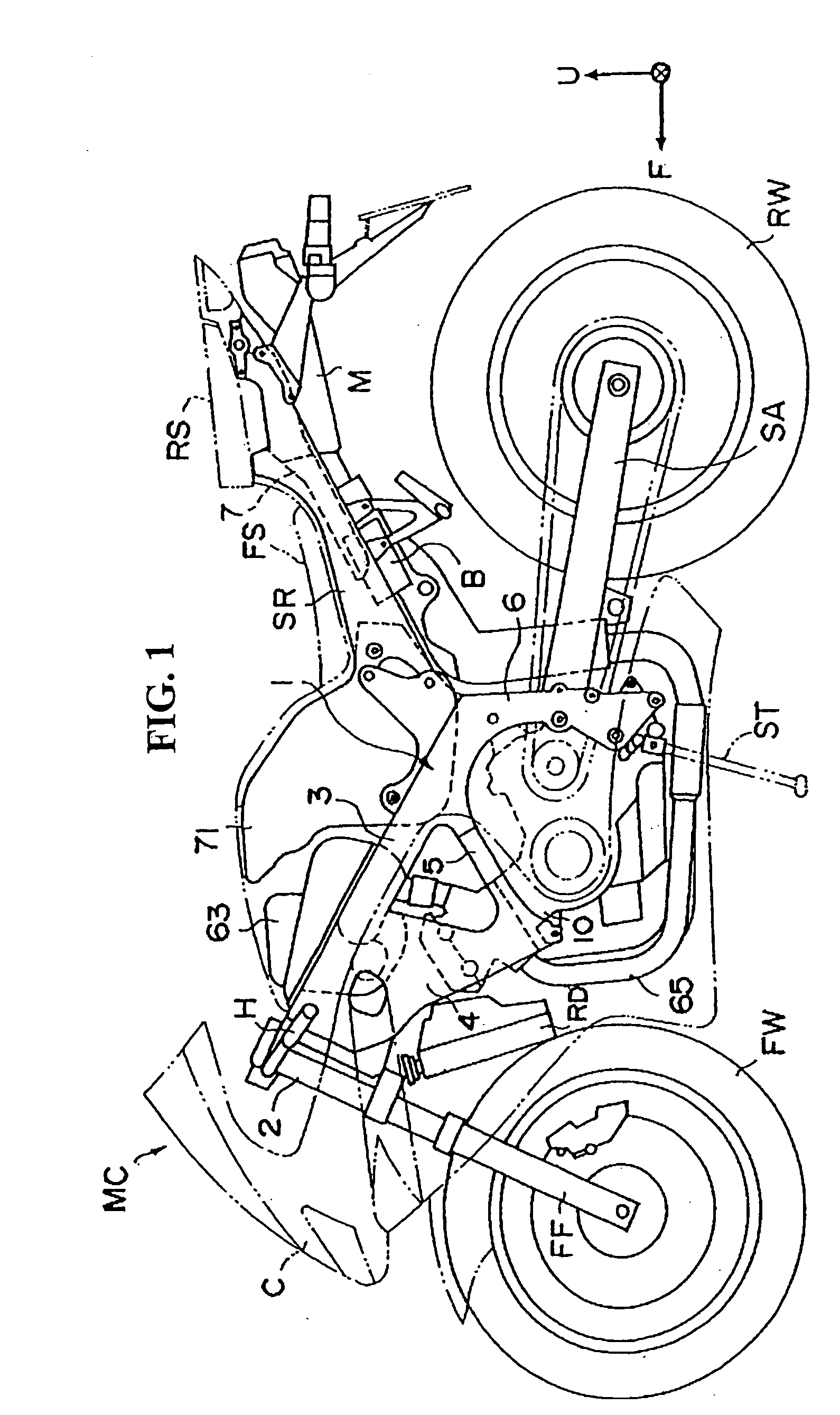
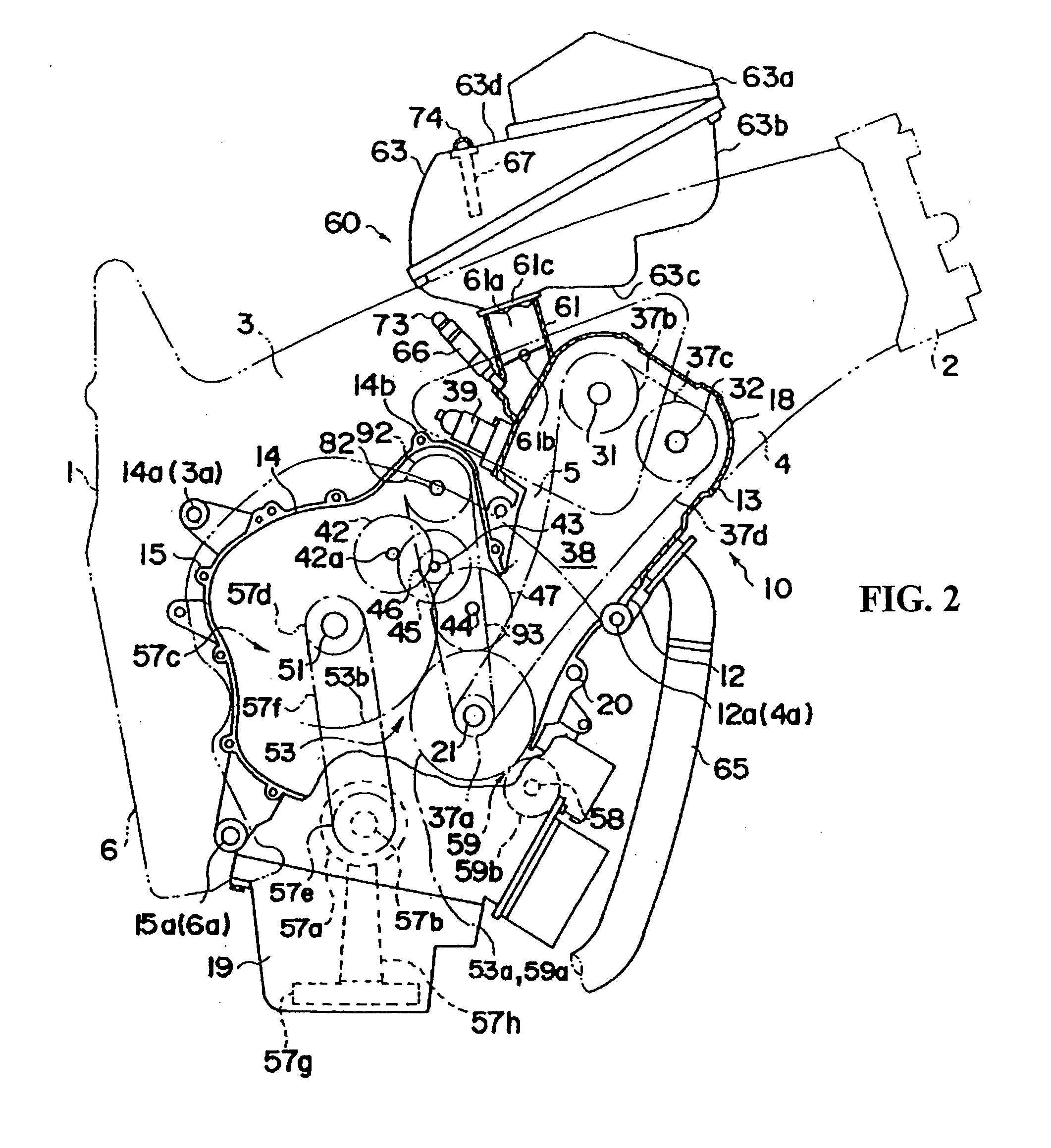
[0050]FIGS. 2 to 8 illustrate aspects of the engine 10 provided with a fuel pump 80 according to the invention. Connection holes 3a, 4a, 6a are formed in rear end portions of the main frames 3. The engine 10 is suspended from the vehicle body frame 1 in the state of being fastened to the connection holes 3a, 4a, 6a, lower end portions of the hangers 4, and lower end portions of the pivot brackets 6, respectively. The engine 10 is contained in an inside space of the vehicle body frame 1 surrounded by the frame elements, and is mounted on a central portion in the front-rear direction and the left-right direction and a lower portion, of the motorcycle MC.

[0051]The engine 10 is a 4-stroke parallel 4-cylinder reciprocating engine, which includes a crankcase 20, a cylinder block 12 and a cylinder head 13, arranged in this order from the lower side thereof. In describing the parallel 4-cylinder engine 10 hereinafter, in order to specify the positions of the members (cylinder bores, pistons...

second embodiment

[0104]The cam chain 137d in the second embodiment is not limited to the link type chain, insofar as a sprocket can be engaged therewith also from the outer side; for example, a double-sided cog belt may also be adopted.

[0105]A fuel pump 280 according to a third embodiment will now be described with reference to FIGS. 10 and 11. In the third embodiment, like the second embodiment, the basic structure of the engine 10 and the vehicle body frame 1 are the same as in the first embodiment.

third embodiment

[0106]In the third embodiment, a cam 291 is integrally rotatably provided at the outer periphery of a crank web formed on the right side of a second crank pin 21b. The cam 291 is set so that a cam lobe peak 291a is located on the lower side when a second piston 24 is located at its bottom dead center, and so that the cam lobe peak 291a is located on the upper side when the second piston 24 is located at its top dead center. In addition, the side surfaces of the cam 291 are provided with through-holes 291b, 291b penetrating in the left-right direction, whereby a reduction in cam weight is obtained.

[0107]The fuel pump 280 in the third embodiment includes a pump body 281, and a plunger 283 contained in a plunger containing part formed in the pump body 281, but the pump drive shaft that was present in the first embodiment is omitted in the third embodiment.

[0108]The pump body 281 is attached, from the upper outer side, to an upper wall 14c of an upper case half 14 on the left side of a ...


PUM


Abstract

An engine-mounted mechanical fuel pump for an internal combustion engine contributes to a stable operation of the engine, a reduction in the weight of the engine, and a reduction in the pump drive loss. The engine includes a cylinder head provided with intake ports and exhaust ports therein, and fuel injection valves for injecting fuel into the inside of a tubular intake air routing assembly connected to the intake ports. A fuel pump is provided on the rear side of a cylinder block and on the upper side of a crankcase, in an arrangement where the intake ports are formed to extend rearwardly and the exhaust ports are formed to extend forwardly from the cylinder head. In one embodiment, the fuel pump is provided on the front side of the cylinder block, where the intake ports are formed to extend forwardly and the exhaust ports are formed to extend rearwardly.

Description

CROSS-REFERENCE TO RELATED APPLICATIONS[0001]The present invention claims priority under 35 USC 119 based on Japanese patent application No. 2006-100782, filed on Mar. 31, 2006. The subject matter of this priority document is incorporated by reference herein.BACKGROUND OF THE INVENTION[0002]1. Field of the Invention[0003]The present invention relates to an internal combustion engine provided with a fuel pump, and to a vehicle including same. The fuel pump supplies fuel to a fuel injector, which in turn injects the fuel into an intake air routing assembly of the engine. More particularly, the present invention relates to an engine having an improved fuel pump configuration and location, and to a vehicle incorporating the engine and fuel pump.[0004]2. Description of the Background Art[0005]Known vehicular fuel delivery systems exist in which a fuel pump is provided for delivering fuel from a fuel tank to an engine, and a fuel metering device, such as a carburetor, an injector, etc. is...

Claims


Application Information

Patent Timeline
Patent Type & Authority Applications(United States)
IPC IPC(8): F02M37/04F01L1/02F02M51/00
CPCF01L1/022F01L1/024F01L1/143F01L1/46F01L1/462F01L2001/0537F02M69/044F02M37/04F02M39/02F02M59/102F02M63/029F02M69/043F02M37/0052
Inventor UEDA, HIROYATAKAHASHI, KATSUNORIKUNIKIYO, KATSUHIRO
Owner HONDA MOTOR CO LTD
Why Eureka
Try Eureka