
Method of fracturing a coalbed gas reservoir

a gas reservoir and coalbed technology, applied in the field of coalbed methane, can solve the problems of reducing the wellbore skin effect, dislodging coal chips, and reducing the efficiency of fracturing fluid during the fracturing process, and achieve the effect of improving the efficiency of fracturing fluid

Inactive Publication Date: 2007-10-04
SCHLUMBERGER TECH CORP
View PDF11 Cites 75 Cited by
  • Summary
  • Abstract
  • Description
  • Claims
  • Application Information

AI Technical Summary

Benefits of technology

[0035]The invention introduces a new hydraulic fracturing method for coal seams or coal-bed methane reservoirs. The new method comprises the step of pre-treating the formation with a permeability modifier that changes the formation's physical properties, and increases the fracturing fluid efficiency. Higher fluid efficiency leads to greater fracture extension into the coal reservoir, less damage to the cleat network, and higher production rates of water (during dewatering) and of gas (during production). This invention is a new method of enhancing the effectiveness of existing hydraulic fracturing and coal-bed methane well stimulation treatments. This method can be combined with other known methods for CBM reservoir fracturing techniques or CBM stimulation as referred to above.
[0036]Specifically, at the initial stages of the hydraulic fracturing treatment, a permeability modifier is injected into the formation that swells the formation, rendering the coal seams significantly less permeable. Subsequently injected fluids will have a higher efficiency in generating fractures and will be less likely to leak-off into the coal formation. They will be capable of extending the hydraulic fracture further away from the wellbore. A longer fracture in turn will enable a larger portion of the coal seam to be produced from a single wellbore-both economically and environmentally attractive. The permeability modifier is usually injected below or at the fracture pressure of the formation. However it may also be advantageous to inject the modifier above frac pressure, or initially at below pressure to swell the near wellbore, and then later at above fracture pressure to initiate and extend a fracture.
[0038]The injected fluid is used to swell the formation at the beginning of the stimulation treatment to improve the efficiency of the fracturing fluid. In preferred embodiments subsequent injections or longer shut-in periods are not required.
[0039]In a variant of the invention, a post-stimulation flush is contemplated using a fluid that will reverse the swelling caused by the swelling agent. It may be more advantageous to replace this post-stimulation flush by adding a suitable de-swelling agent with a delayed release mechanism to the original swelling agent to ensure that all areas contacted by swelling agent are also contacted with de-swelling agent

Problems solved by technology

The procedure reduces the wellbore skin effect.
The over-pressured coal zones provide a pressure surge into the wellbore (a “controlled blowout”), and the resulting stress causes dislodgement of coal chips and carries the chips up the well.
Fracturing fluid leak-off through the cleat network during the fracturing process is a major limitation of modern hydraulic fracturing methods in CBM reservoirs.
For obvious reasons, low fracturing fluid efficiency is undesirable.
Expense and waste aside, the leaked off fluid can substantially reduce the permeability of the cleat network and defeat the benefit of the stimulation treatment.
Moreover, due to various operational constraints (such as maximum injection pressure, maximum injection rate, cost, etc.) low fluid efficiency limits the fracture length that may be achieved.
Injecting the fracturing slurry at higher flow rates can compensate for leak-off losses, but the leaked off fluid may be trapped in the cleats, blocking the pathway through which reservoir fluids can flow from the reservoir to the wellbore.
The presence of water in a porous medium reduces the flow capacity of that medium to other immiscible fluids such as oil or gas.
In the case of CBM reservoirs, water from the injected hydraulic fracturing fluids can infiltrate the cleat network and negatively impact the surface properties (mainly wettability) of the coal.
These changes can result in reduced dewatering and lead to coal fines migration, which can plug the cleats.
These surfactants are delivered in the fracturing fluid and result in more rapid coal dewatering and fracturing fluid recovery out of the fracture.
Liquid CO2 or foams / emulsions created by mixtures of CO2 and nitrogen are reported to be undamaging because the fluid will vaporize and be produced after the treatment.
This increased fracture void volume increases coal-bed permeability and resultant increase in methane gas flows.

Method used


Image

  • Method of fracturing a coalbed gas reservoir
  • Method of fracturing a coalbed gas reservoir
  • Method of fracturing a coalbed gas reservoir

Examples


Embodiment Construction

[0043]The invention proposes a pre-fracturing treatment of a well in one or more subterranean coal seams. Prior to the fracturing a fluid is injected below or at fracturing rates and pressures. The fluid is designed to swell the coal and prevent fracturing fluid leak-off into the cleat network of the coal seam. This has the dual effect of protecting the cleats against damaging fracturing fluids, and, more importantly, improving the efficiency of the fracture propagation process so longer hydraulic fractures result.

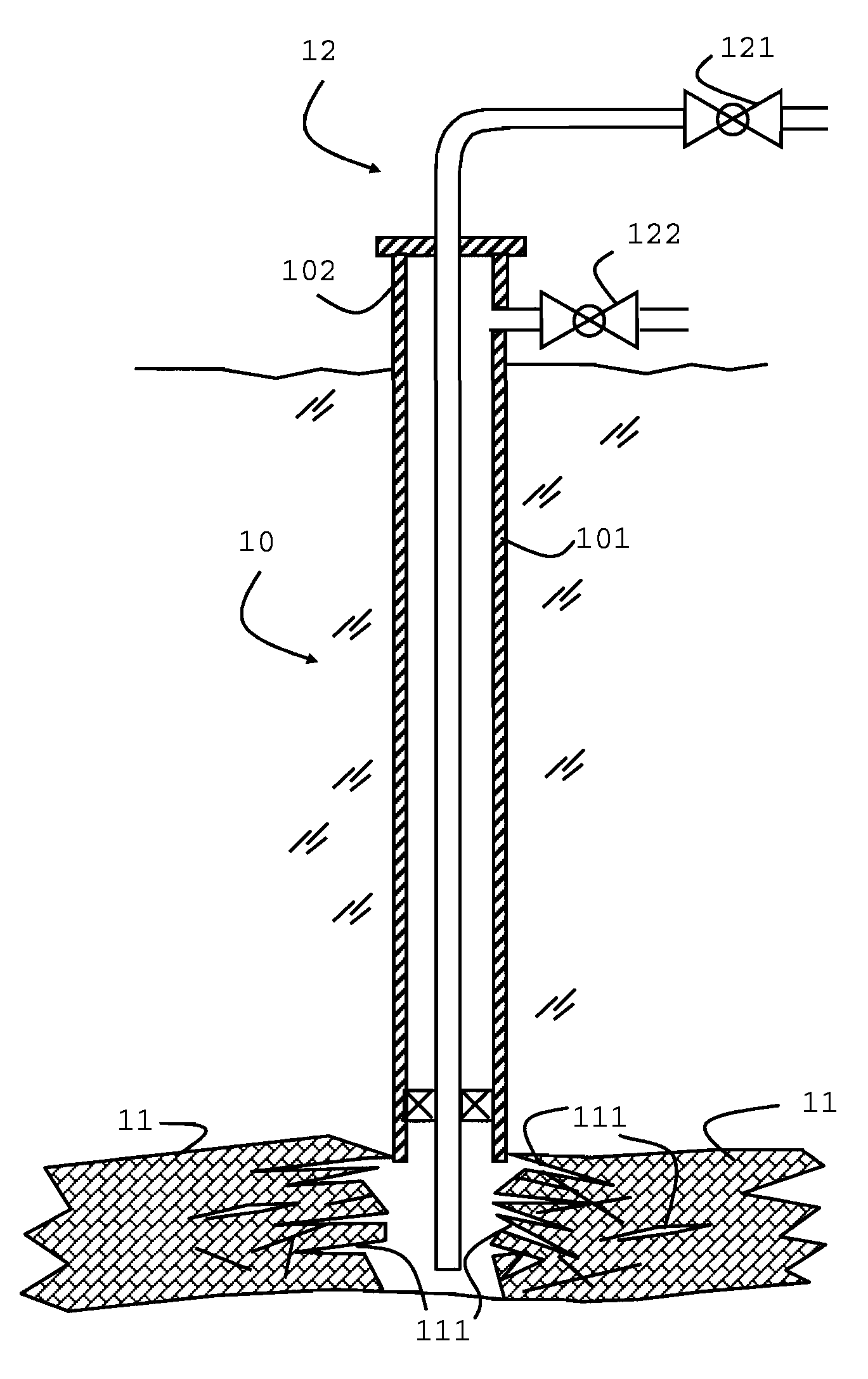
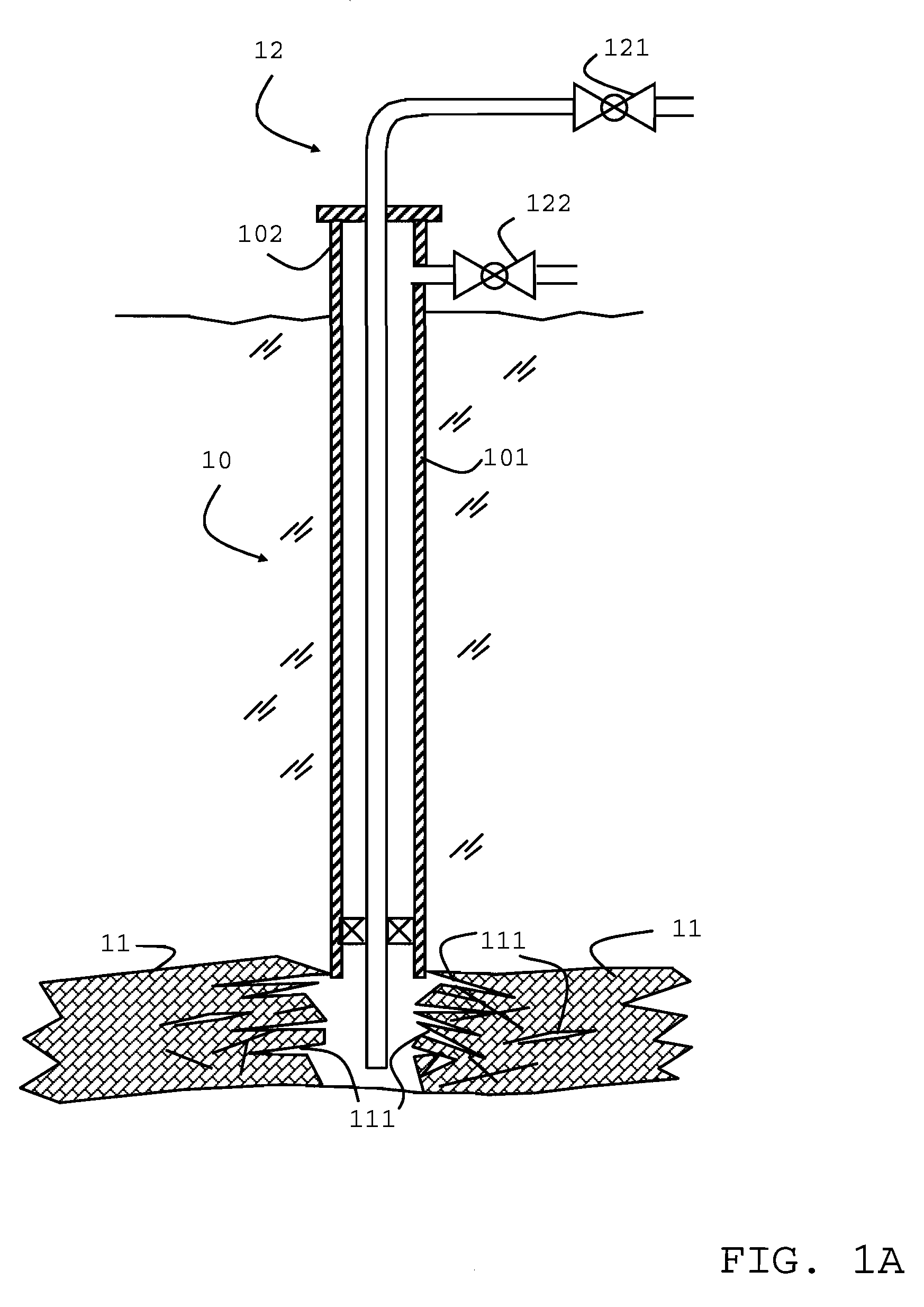
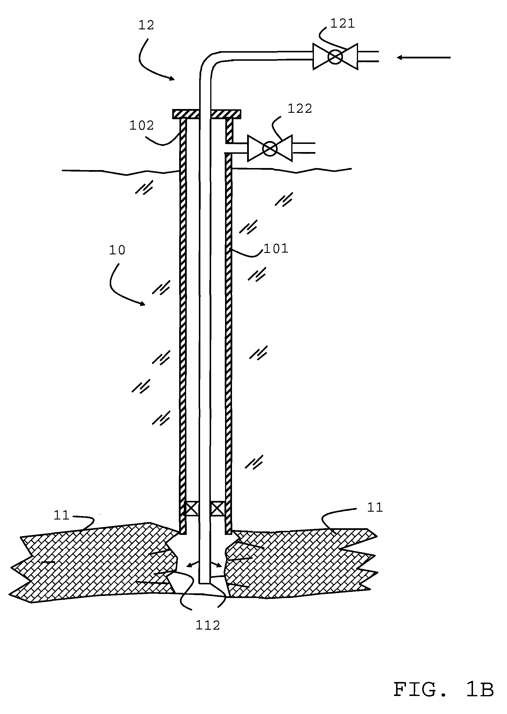
[0044]A more complete listing of the steps of a method in accordance with an example of the invention are shown in the stages as shown in FIG. 1 and the flow chart of FIG. 2 and are listed together with possible variants and alternatives in the following.

[0045]FIG. 1A shows a well 10 drilled into a coal seam 11. The well is shown with a casing 101, but the invention equally applies to uncased or open wells. Surface flow control equipment 12 includes injection tubing 120 an...


PUM


Abstract

A method for stimulation of gas production from coal seams is described using a permeability modifier, such as a coal swelling agent, injected into the coal seams via a wellbore to reduce the permeability of the coal seams prior to a fracturing treatment.

Description

[0001]The present invention relates to methods for enhancing the production of gas released from coal seams and the like. The present invention relates to methods of fracturing a coal seam gas reservoir using the injection of a fluid with a swelling agent or a mixture of swelling agents.BACKGROUND OF THE INVENTION[0002]Subterranean coal seams contain substantial quantities of natural gas, primarily in the form of methane. Such reservoirs are commonly referred to as coal-bed methane (CBM) reservoirs. To effectively produce gas from CBM reservoirs, one or more stimulation methods are used to increase the output.[0003]The most common CBM stimulation methods include directionally drilling parallel to the bedding of the seam, the creation of a cavity in a coal seam, or hydraulic fracturing of the coal.[0004]Directional drilling involves angling the drill stem so that drilling is not vertical but will parallel the coal seam. Because the bore hole trends along the formation, a greater area...

Claims


Application Information

Patent Timeline
IPC IPC(8): E21B43/267E21B43/26E21B33/13
CPCC09K8/62E21B41/0064Y02C10/14E21B43/26E21B43/006Y02C20/40
Inventor MILLER, MATTHEWNAGL, MICHAELAENGLAND, KEVINBROWN, ERNESTTIBBLES, RAYMONDTUSTIN, GARY
Owner SCHLUMBERGER TECH CORP
Learn More