Mechanical-Quality measuring device

a measuring device and mechanical technology, applied in the direction of force measurement using piezo-resistive materials, acceleration measurement using interia forces, instruments, etc., can solve the problems of inability to use a chip for measuring a state of strain in the stress concentration field, inability to meet the requirements of high accuracy,

Active Publication Date: 2007-10-04
HITACHI LTD
View PDF3 Cites 46 Cited by
  • Summary
  • Abstract
  • Description
  • Claims
  • Application Information

AI Technical Summary

Benefits of technology

[0006]In measuring a torque and an axial force of the rotation axis simultaneously, it is theoretically possible to adhere two pieces of strain measuring chips to the rotation axis and do the measurement, as written in Patent Document 2 and the like. However, if two pieces of the st...

Problems solved by technology

However, if two pieces of the strain measuring chips are adhered respectively so as to measure shearing strain and normal strain, the measurement is adversely affected by variation of two chips generated in the adhering, therefore, there is a problem that this technique is not suited for the measurement of high accuracy.
Similarly, if two strain measuring chips are adhered respectively so as to measure shearing strain and normal strain, in reality, it become easy to generate an error in the adhering angle, therefore, there is a problem that this technique is not suited for t...

Method used


Image

  • Mechanical-Quality measuring device
  • Mechanical-Quality measuring device
  • Mechanical-Quality measuring device

Examples


example 2

(2) EXAMPLE 2

Biaxial Separation Chip

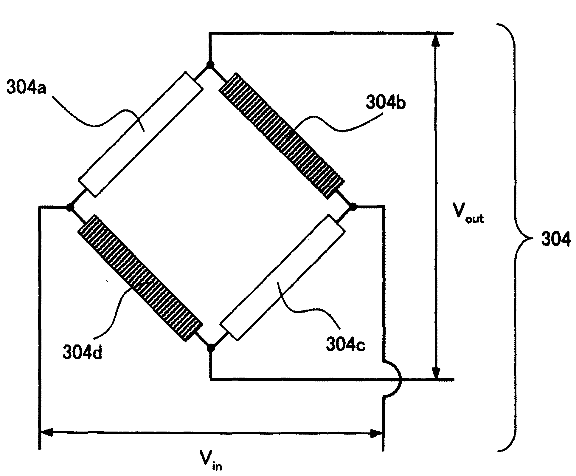
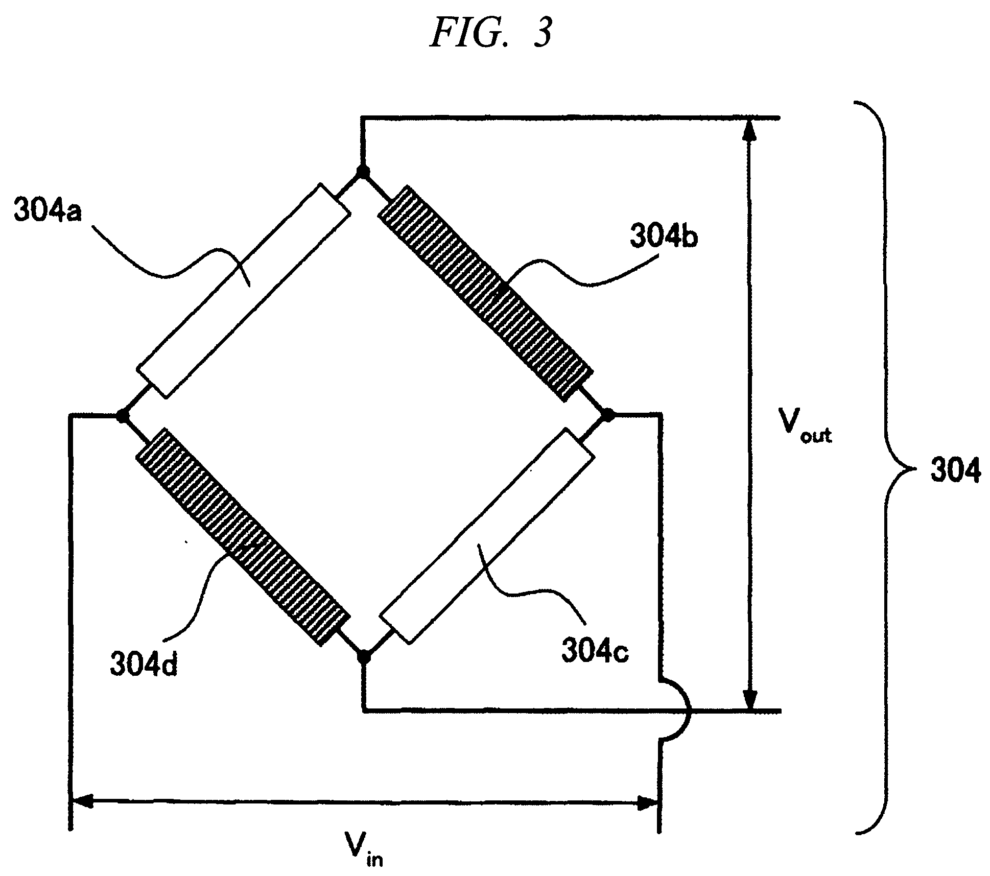
[0016]To measure the multiaxial strain field with high precision, the bridge circuit is composed of a combination of two diffusion resistors with high sensitivity for strain and two diffusion resistors with low sensitivity for strain. Here, the diffusion resistor (impurity diffusion layer) with high sensitivity for strain is, for example, an n-type diffusion resistor in which the direction of electric current is in parallel with the direction or a p-type diffusion resistor in which the direction of electric current is in parallel with the direction, while the diffusion resistor (impurity diffusion layer) with low sensitivity for strain is, for example, a p-type diffusion resistor in which the direction of electric current is in parallel with the direction or an n-type diffusion resistor in which the direction of electric current is in parallel with the direction. And, the direction of electric current is preferably made into the longitudinal d...

example 3

(3) EXAMPLE 3

Adjusting Resistor

[0023]Further, more preferably, p-type diffusion resistors with relatively low resistance for adjustment of resistance value are connected in series to the p-type diffusion layer in the bridge circuits. That is, the number of lead wires led from the end portion of the p-type diffusion resistor to the outside of the bridge circuit is made larger than the number of lead wires led from the end portion of the n-type impurity diffusion resistor to the outside of the bridge circuit, and actual values of resistance of the p-type impurity diffusion resistor and the n-type impurity diffusion resistor are measured, then the lead wires to be used for measurement. By forming the adjusting resistor in this manner, it is possible to correct an error occurred in manufacturing of each diffusion layer resistance value caused by difference in the forming process of the p-type diffusion layer and the n-type diffusion layer. As a result, the advantages that the output off...

example 4

(4) EXAMPLE 4

Polysilicon Resistor Bridge

[0024]Similarly, to measure the multiaxial strain field with high precision, the wheatstone bridge circuit composed of the impurity diffusion resistors are provided at least two sets on the same semiconductor substrate, and the two sets of the wheatstone bridge circuits are made to include a p-type impurity diffusion register in which the direction of electric current and measuring the variation of the resistance value is in parallel with the direction of the semiconductor monocrystalline substrate, and a polysilicon wiring resistor.

[0025]The p-type diffusion resistor in which the direction is a longitudinal direction has no sensitivity for the stain of each direction, and the polysilicon resistor has a high sensitivity in the longitudinal direction only. Hence, the direction in which the current of the polysilicon wiring resistor composing the first wheatstone bridge flows and the variation of the resistance value is measured and the direct...


PUM


Abstract

A mechanical-quantity measuring device capable of measuring a strain component in a specific direction with high precision is provided.
At least two or more pairs of bridge circuits are formed inside a semiconductor monocrystal substrate and a semiconductor chip, and one of these bridge circuits forms a n-type diffusion resistor in which a direction of a current flow and measuring variation of a resistor value are in parallel with a <100> direction of the semiconductor monocrystal silicon substrate, and an another bridge circuit is composed of combination of p-type diffusion resistors in parallel with a <110> direction.

Description

CROSS-REFERENCE TO RELATED APPLICATION[0001]The present application claims priority from Japanese patent application No. JP 2006-089834 filed on Mar. 29, 2006, the content of which is hereby incorporated by reference into this application.TECHNICAL FIELD OF THE INVENTION[0002]The present invention relates to a device capable of measuring a mechanical quantity of an object and a system using this device.BACKGROUND OF THE INVENTION[0003]As a technique for measuring a deformation (strain) of a measuring object, a technique has been known in which a metallic foil strain gauge is used by making use of the fact that a resistance value of the metallic foil changes by a strain. This is a technique, in which this strain gauge is adhered to the measuring object, and a length of the metallic foil is changed according to the strain of the measuring object, and as a result, and by detecting the changing resistance value of the metallic foil, the strain of the measuring object can be measured.[00...

Claims


Application Information

Patent Timeline
IPC IPC(8): H01L27/20H01L29/84
CPCG01B7/18G01L1/2293G01L1/18G01B7/16
Inventor SHIMAZU, HIROMIOHTA, HIROYUKITANNO, YOHEI
Owner HITACHI LTD
Why Eureka
Try Eureka