Cooling of stator windings

a technology of stator windings and windings, which is applied in the direction of windings, magnetic circuit rotating parts, magnetic circuit shapes/forms/construction, etc., can solve the problems of obstructing the free flow of heat out of the conductor, thermal insulation, and large heat generation of large power motors, so as to reduce the temperature of stator coils, and facilitate heat conductivity

Inactive Publication Date: 2007-10-04
PRECISION MAGNETIC BEARING SYST
View PDF17 Cites 17 Cited by
  • Summary
  • Abstract
  • Description
  • Claims
  • Application Information

AI Technical Summary

Benefits of technology

[0012] To reduce the temperature of stator coils, one side of the coil conductor has the insulation removed exposing the bare copper. The conductor insulation insulates against both electric and heat transfer. By removing the insulation from the conductor and placing the conductor wire in contact with a material that easily conducts heat but acts as an insulation to the flow of electricity, the temperature of the stator coils can be reduced. A thermally conductive ceramic substrate such as alumina or aluminum nitride or beryllium oxide and a thermal epoxy can be used to contact and position the stator coil in place.
[0013] The combined effect of bared copper, thermally conductive ceramic substrate and thermal epoxy without smear reduces the hot spot temperature. A cooler coil in turn allows significant reduction in the weight of the motor and increases the power density.

Problems solved by technology

Large power motors generate proportionally large amounts of heat.
These coatings, while effective as electrical insulators, unfortunately are also thermally insulative, and obstruct free flow of heat out of the conductors.
As a result, the conductors used in the prior art motors see a large rise in temperature.
The situation is worsened further when the coil is made by packing a large number of conductors inside a coil window or iron slot.
Hot spot conductors are the first to fail because of thermal degradation of insulation.
If the hot spot temperature exceeds the temperature rating of the insulation, it will start failing.
However, this material is electrically conductive, and had to be covered by two electrically insulating layers.
Thus, even though pitch composite has high thermal conductivity, its insulation layer will obstruct heat flow, increasing thermal resistance.
Such copper strips however are in the path of alternating fields and hence generate eddy losses.
Packing of copper protrusions at less than 0.25 in. spacing, as proposed by Liebe, will degrade cooling effectiveness.

Method used


Image

  • Cooling of stator windings
  • Cooling of stator windings
  • Cooling of stator windings

Examples


Embodiment Construction

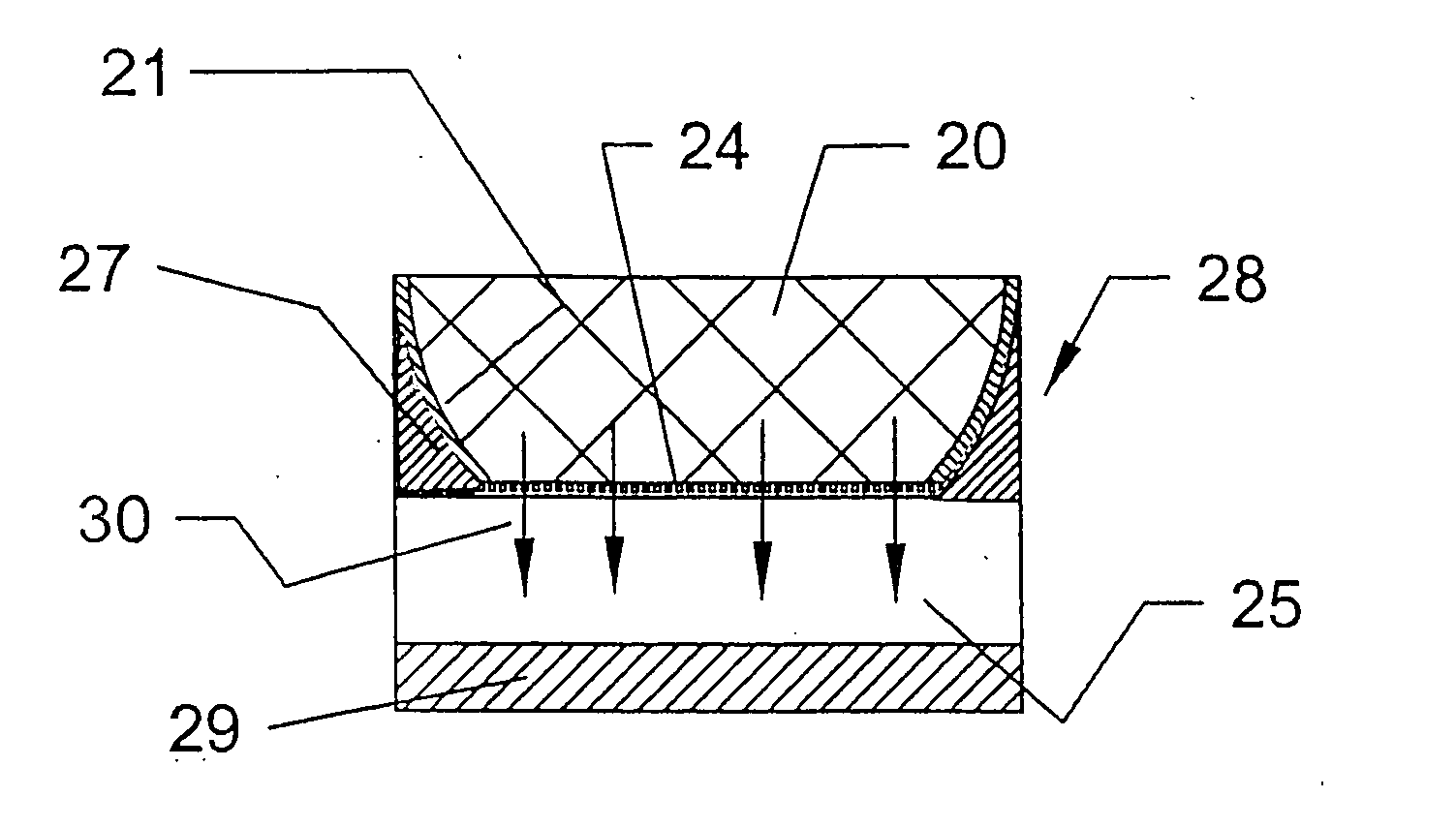
[0021] A central theme of this invention is to present a novel configuration that meets the goal of reducing hot spot temperatures.

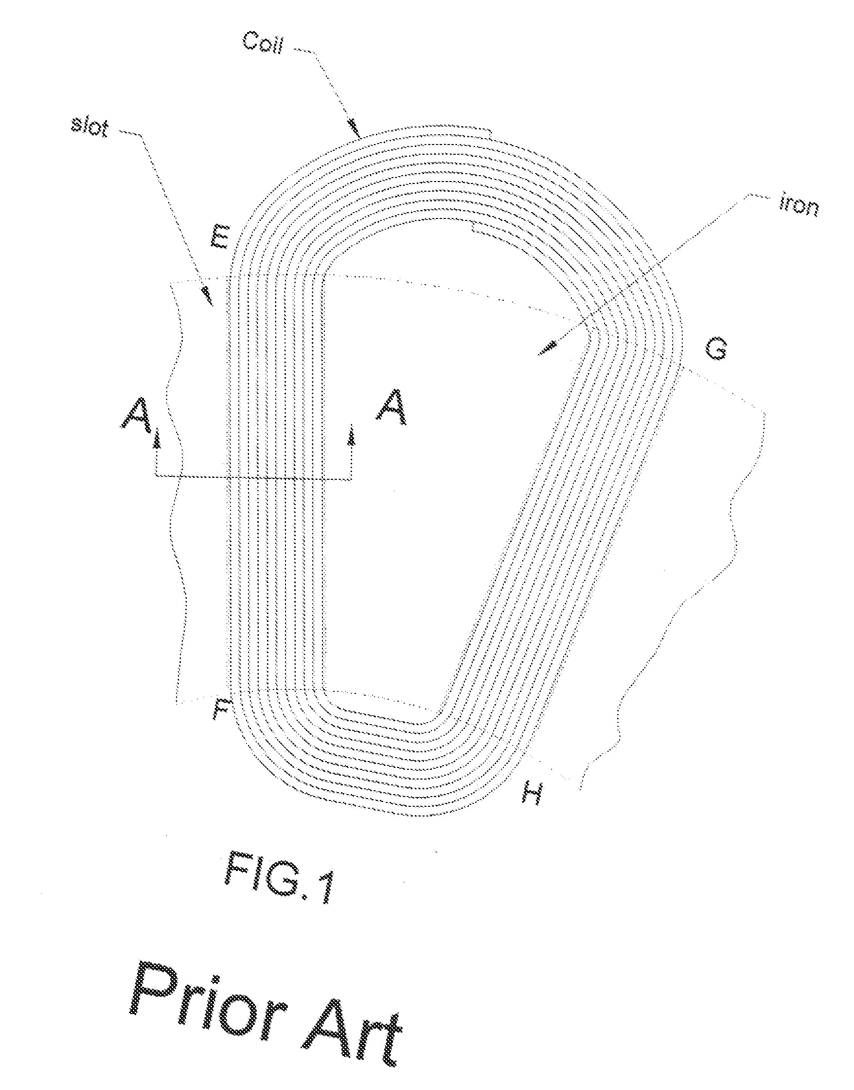
[0022]FIG. 1 shows a plan view of a prior art coil that lies within a slot of an iron stator of an axial gap motor. Each turn is made of two straight segments EF and GH and two round segments EG and FH, called end windings. The straight segments EF and GH sit within a slot in the iron stator, while end windings EG and FH sit outside of or beyond the iron stator.

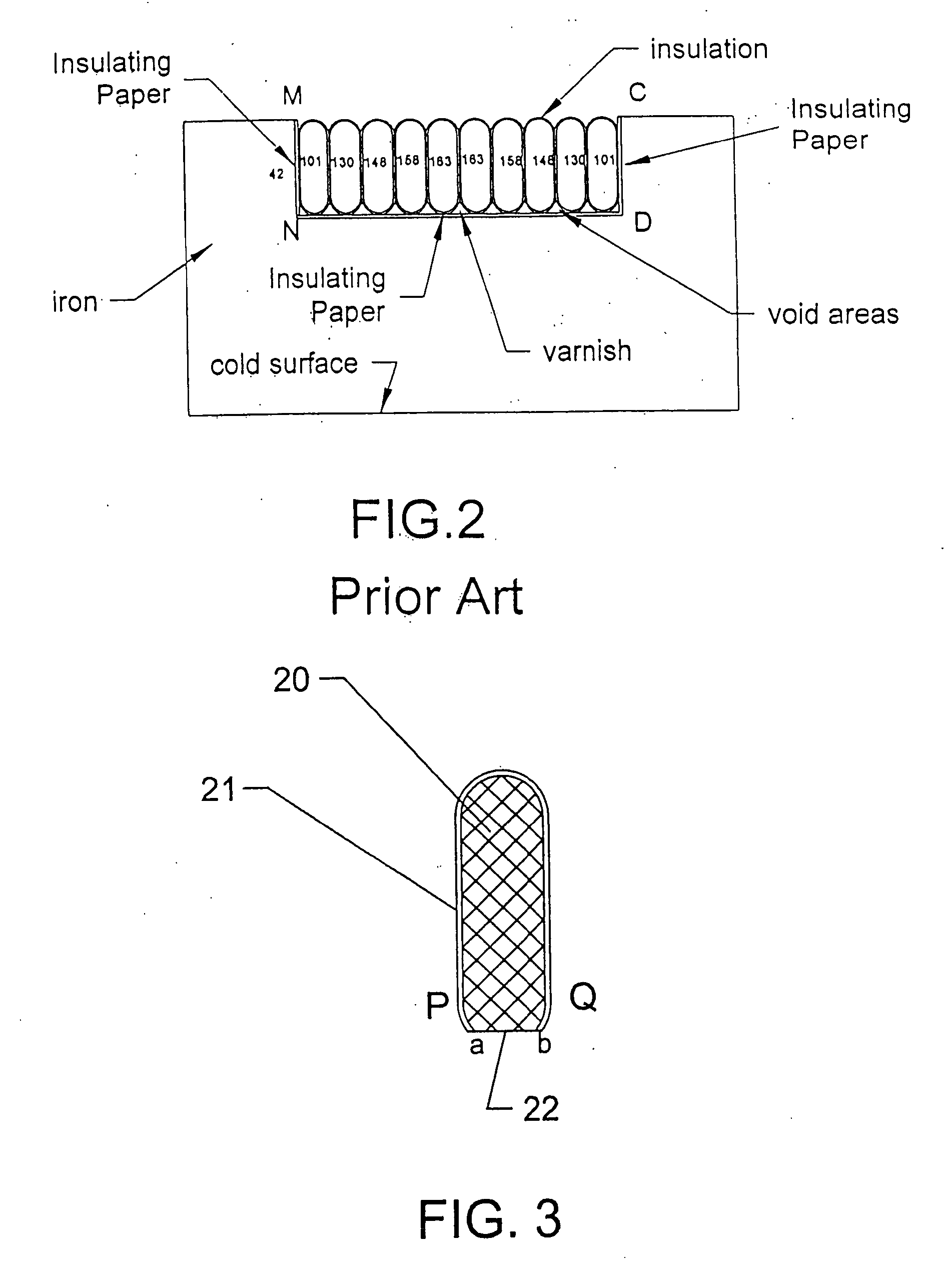
[0023]FIG. 2 is a cross-section along the section line A-A of FIG. 1 showing the coil within the slot of an iron core. The slots are lined by an insulating paper such as NOMEX®, and the void areas not occupied by the coil wires are filled with varnish. Also shown are temperatures of various conductors when heat is removed by a cold surface at the bottom. The slot itself has three edges, two vertical and one horizontal; the top may be opened to air. The two vertical edges MN and CD are lined with...


PUM

PropertyMeasurementUnit
temperatureaaaaaaaaaa
thermal resistanceaaaaaaaaaa

Abstract

An arrangement for cooling an electric motor's stator winding coil is described. One area of a conductor insulation is removed to expose the copper conductor. The conductor is wound into a coil with bared, exposed conductor areas facing inward. The vertical edges of a slot or recess in an iron stator are lined with electrically insulating paper. A thermally conductive electrically insulating, ceramic substrate is bonded to the floor or base of the slot. The coil is inserted within the slot over the ceramic substrate with the exposed conductor facing and contacting the ceramic substrate. The coil is bonded to the ceramic substrate by thermally conductive and electrically insulative epoxy that fills the voids between the two. Heat flows from the conductor, through the bared copper surface, into the ceramic and the iron core stator with little resistance. A ceramic strip can be used alone or with copper traces bonded to the ceramic or conductor bared surface. Using a thermally conductive epoxy bond reduces resistance due to epoxy smear and reduces thermal resistance of the heat transfer path.

Description

BACKGROUND OF THE INVENTION [0001] 1. Field of the Invention [0002] The invention is to cooling a coil by shaving off the insulation from an area on the conductor and contacting the bared conductor area with a thermally conductive electrically insulative ceramic to transfer heat away from the conductor and coil. [0003] 2. Description of Related Art [0004] Large power motors generate proportionally large amounts of heat. Their conductors, usually copper, are insulated by thin electrically insulating coatings or tape. These coatings, while effective as electrical insulators, unfortunately are also thermally insulative, and obstruct free flow of heat out of the conductors. As a result, the conductors used in the prior art motors see a large rise in temperature. The situation is worsened further when the coil is made by packing a large number of conductors inside a coil window or iron slot. The conductors remote from the cooler window boundaries (those near the center of the coil window...

Claims


Application Information

Patent Timeline
Patent Type & Authority Applications(United States)
IPC IPC(8): H02K1/04H02K9/00H02K3/24
CPCH02K3/12H02K9/22H02K3/345H02K3/18H02K9/223
Inventor RAO, DANTAM K.
Owner PRECISION MAGNETIC BEARING SYST
Why Eureka
Try Eureka