Optical transmission apparatus

a transmission apparatus and optical technology, applied in the direction of electrical apparatus, transmission monitoring/testing/fault measurement system, wavelength-division multiplex system, etc., can solve the problem of low possibility of erroneously detecting a loss of signal light, slow system performance, and low initial start-up time. achieve the effect of improving speed and stability

Inactive Publication Date: 2007-10-04
FUJITSU LTD
View PDF15 Cites 19 Cited by
  • Summary
  • Abstract
  • Description
  • Claims
  • Application Information

AI Technical Summary

Benefits of technology

[0020]It is accordingly an object of the present invention to provide an optical transmission apparatus capable of normally detecting a signal light discon...

Problems solved by technology

Noting that in an optical add-drop system, when an optical signal transmitted from a branch station and an optical signal transmitted from a terminal station are coupled by a branching unit, an S/N ratio of the optical signal whose optical power is lower is deteriorated when the optical power levels are different from each other, worsening the system performance, there has been known an optical communication system that adjusts the power levels of the optical signals by transmitting a dummy light together with the optical signal from the branch station, or adjusts the levels of both of the added optical signals to be equalized, when optical signals are added, by providing a branching unit with an optical attenuator or an active optical signal level a...

Method used


Image

  • Optical transmission apparatus
  • Optical transmission apparatus
  • Optical transmission apparatus

Examples


embodiment

[3]

FIGS. 11 and 12

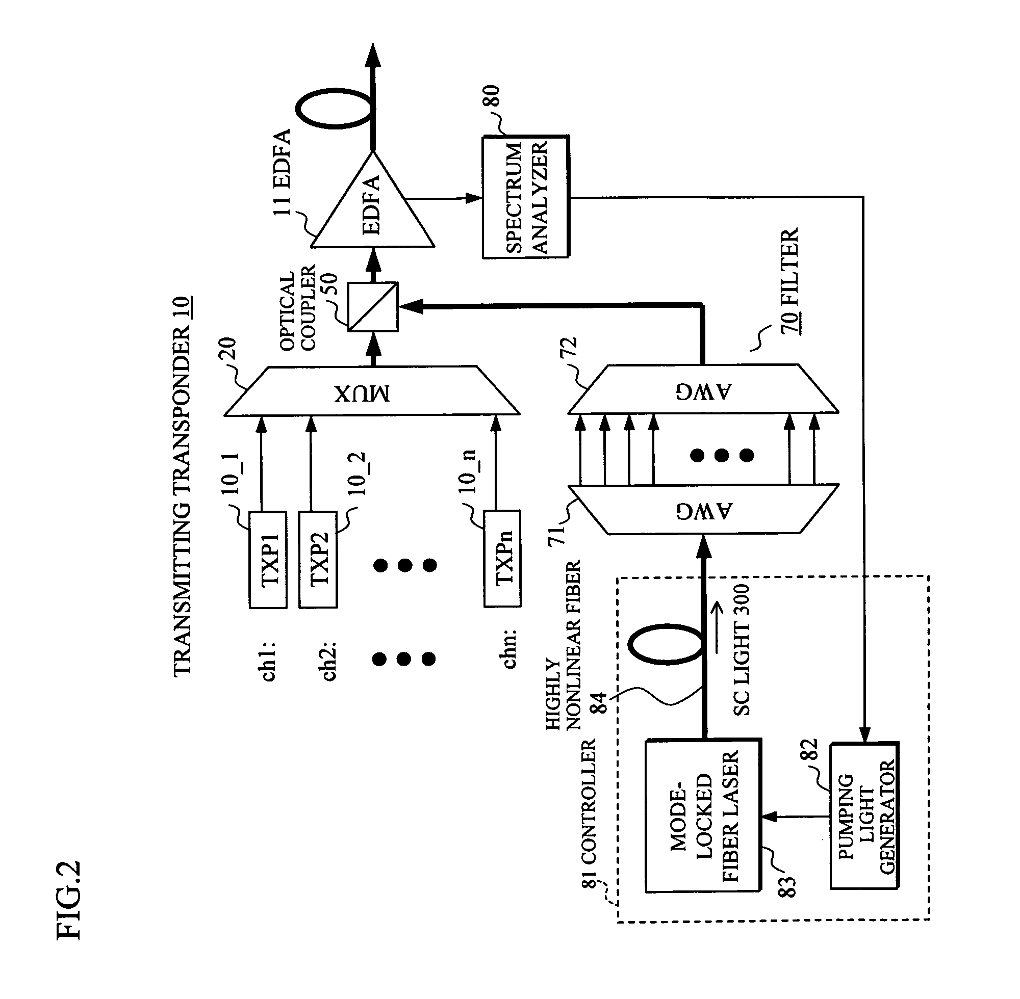
[0078]In this embodiment [3], the controller 81 is composed of the mode-locked fiber laser 83 and the highly nonlinear fiber 84, and a pumping light generator is not used as in the above-mentioned embodiments [1] and [2]. Instead, a filter 700 and a VOA controller 74 are used to form the controller. The filter 700 is different in that variable optical attenuators (VOAs) 73 are further provided between the AWGs 71 and 72 corresponding to “n” units of channels ch1-chn in the transmitting transponder 10, and that the variable optical attenuators (VOA) 73 are controlled by a VOA controller 74.

[0079]The control flow of this embodiment [3] is shown in FIG. 12. Also in this control flow, the steps S41-S45 basically correspond to steps S1-S5 in FIG. 5A. However, it is different in that the bandwidth of the SC light 300 outputted from the mode-locked fiber laser 60 through the highly nonlinear fiber 84 is controlled by reducing or increasing the optical power of the corresp...


PUM


Abstract

In an optical transmission apparatus, a number of wavelengths of an output light to an optical transmission line and an optical power of each of the wavelengths are detected by a spectrum analyzer, and a power of a super continuum light outputted to a highly nonlinear fiber is controlled by a controller so as to confine the number of wavelengths and the optical power within predetermined ranges. A wavelength component corresponding to a signal light is removed by a filter from the output light from the highly nonlinear fiber, and an output light of the filter and the signal light is coupled by an optical coupler.

Description

BACKGROUND OF THE INVENTION[0001]1. Field of the Invention[0002]The present invention relates to an optical transmission apparatus, and in particular to an optical transmission apparatus performing a long-distance transmission of an optical signal of a plurality of wavelengths by a wavelength division multiplexing (WDM).[0003]2. Description of the Related Art[0004]FIG. 13 shows an example of a previously known wavelength division multiplexing optical transmission apparatus In this prior art example, as shown in a portion (a) of FIG. 13, a wavelength multiplexer (MUX) 20 having received a signal light from a transmitting transponder (TXP) 10 provided per channel ch1 . . . multiplexes wavelengths of the signal light to be transmitted to an optical transmission line.[0005]In the optical transmission line, as shown in FIG. 13, erbium-doped fiber amplifiers (hereinafter, occasionally abbreviated as EDFA) 11-15 are serially connected. Distributed Raman amplifiers (hereinafter, occasionall...

Claims


Application Information

Patent Timeline
IPC IPC(8): H04B10/00H04B10/07H04B10/079H04J14/00H04J14/02
CPCH04B10/506H04J14/0221H04J14/02H04B10/564
Inventor SHIMIZU, YOSHIHIRO
Owner FUJITSU LTD
Why Eureka
Try Eureka