Measuring transducer of vibration-type

Active Publication Date: 2007-10-11
ENDRESS HAUSER FLOWTEC AG
View PDF39 Cites 17 Cited by
  • Summary
  • Abstract
  • Description
  • Claims
  • Application Information

AI Technical Summary

Benefits of technology

[0046] A basic idea of the invention is to achieve the affixing of measuring tubes of a measuring transducer of vibration type in a support element by means of screwed-fittings which are as vibration-resistant as possible. By the use of screwed-fittings, which also are highly pressure resistant, coupled with the use also of sufficiently pressure-resistant measuring tubes, it is possible then to create, in a comparatively simple manner, equally pressure-resistant measuring transducers of the type under discussion. A further basic idea of the invention is to improve the sensitivity of such measuring transducers further by using especially high-strength materials for the respective measuring tube, such as high-strength stainless steel alloys and/or metals additionally strengthened by autofrettage. For this, in turn, the use of screwed-fittings is especially suited, since, in this way, solder, braze or weld connections for the purpose of affixing the respective measuring tube to the support element can be completely avoided. As a result of this, overheating during manufacture of the mea

Problems solved by technology

Apart from the fact that the operational safety of the entire measuring device can depend thereon, already the smallest deviation of the strength of this connection from that which existed at the time of the calibration can lead also to significant, no longer manageable fluctuations of the zero point and, consequently to essentially unusable measurement signals.
Usually, such zero-point errors attributable to loss of strength in the measuring transducer can only be satisfactorily overcome be installation of a new inline measuring device.
As described in U.S. Pat. No. 5,610,342, if the heat supplied to the affixing locations of the measuring tubes with the endpieces during the mentioned welding, soldering or brazing leaves behind, following cooling, a state of mechanical, residual stress, such can lead to stress corrosion cracking, which then more or less weakens the joints and/or the measuring tube material in this way also.
A further problem of such materially bonded, weld, solder or braze connections is mentioned in U.S. Pat. No. 6,519,828 or U.S. Pat. No. 6,598,281, this being material-wearing, oscillatory rubbing in the areas of the joints.
Moreover, as perceivable from U.S. Pat. No. 6,047,457, U.S. Pat. No. 6,168,069, U.S. Pat. No. 6,352,196, U.S. Pat. No. 6,598,281, U.S. Pat. No. 6,634,241, U.S. Pat. No. 6,523,421, or U.S. Pat. No. 6,698,644, problems can arise relative to the permanence of soldered connections, problems which can be traced back to, among other things, insufficient wetting and/or radially alternating, mechanical stressing of the joints.
As a result, often a decrease in the nominal pull-out strength of the measuring tube out of the support element is present.
This c

Method used


Image

  • Measuring transducer of vibration-type
  • Measuring transducer of vibration-type
  • Measuring transducer of vibration-type

Examples


Embodiment Construction

[0055] While the invention is susceptible to various modifications and alternative forms, exemplary embodiments thereof have been shown by way of example in the drawings and will herein be described in detail. It should be understood, however, that there is no intent to limit the invention to the particular forms disclosed, but on the contrary, the intention is to cover all modifications, equivalents, and alternatives falling within the spirit and scope of the invention as defined by the intended claims.

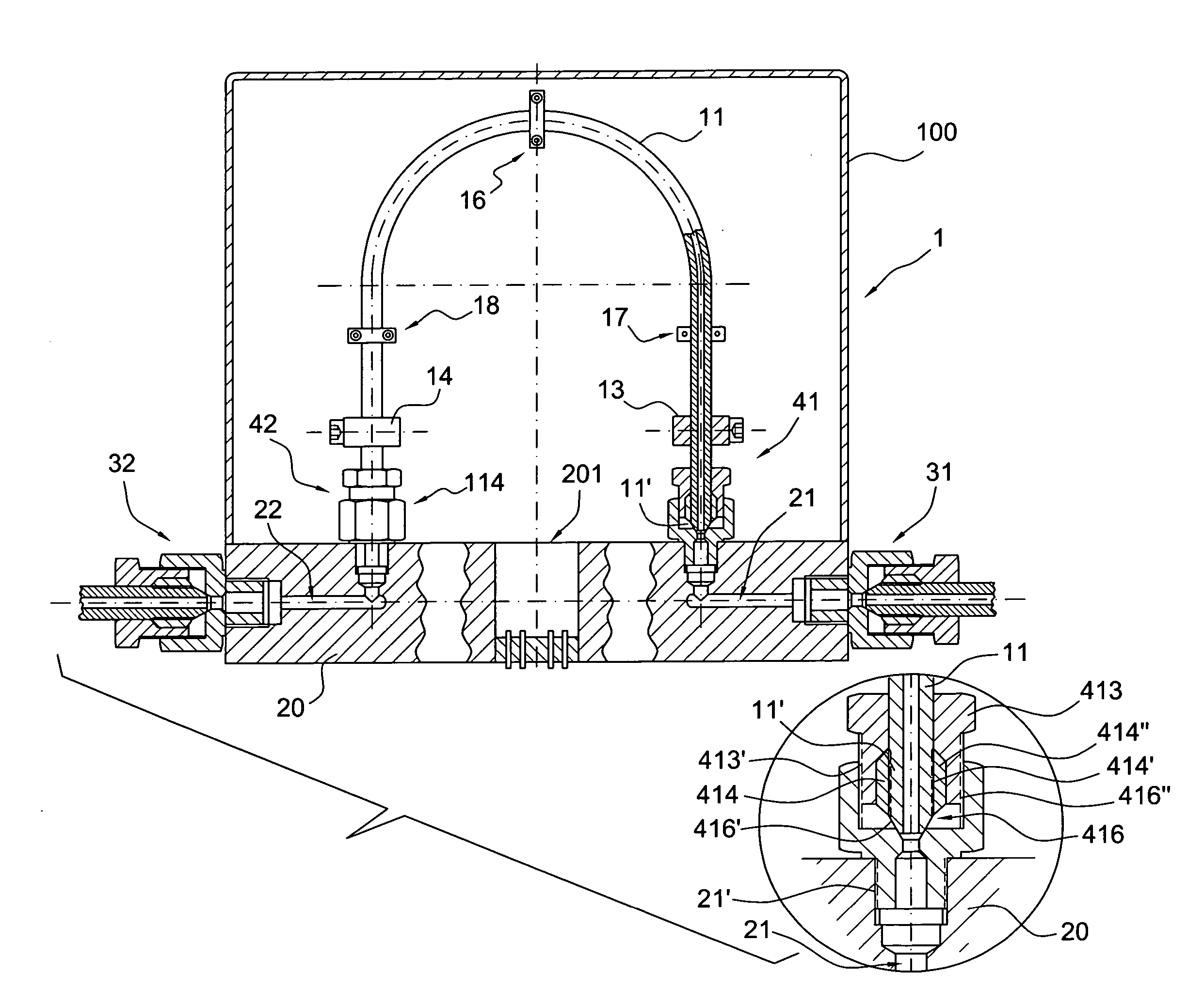
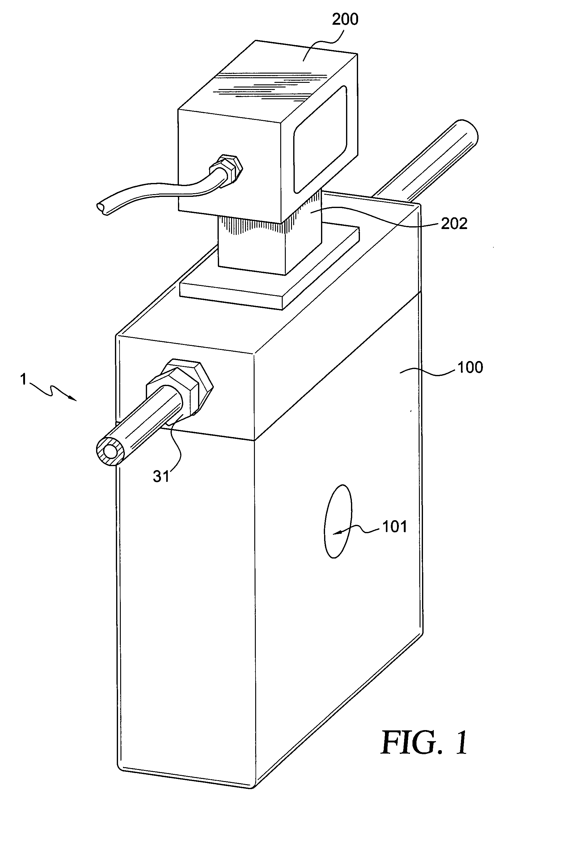
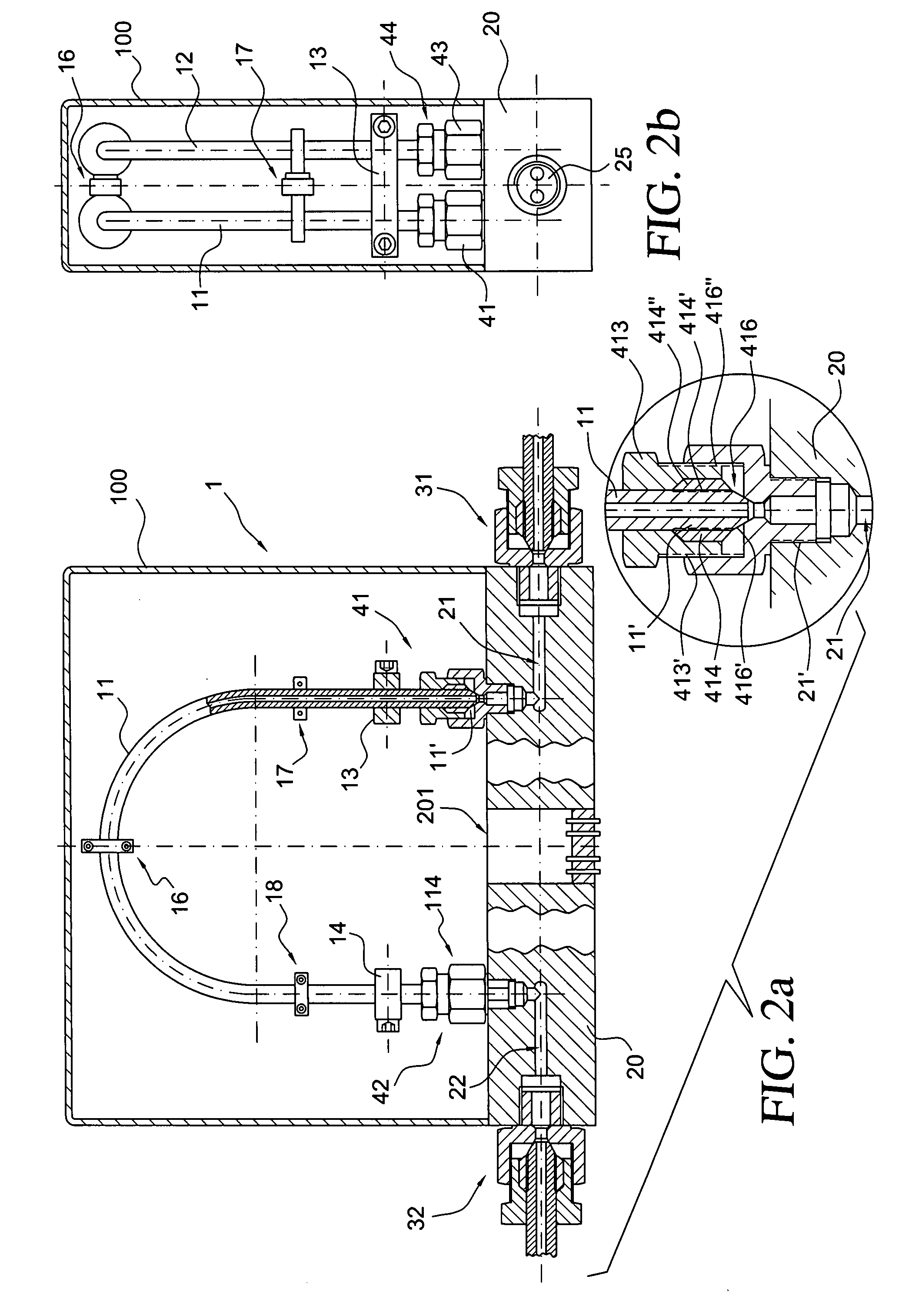
[0056]FIG. 1 shows an inline measuring device insertable into a pipeline, for example a process line of an industrial plant. The inline measuring device is constructed, for instance, in the form of a Coriolis mass flow measuring device, density measuring device, viscosity measuring device or the like, serving for the measuring and / or monitoring of at least one parameter, for example a mass flow, density, viscosity, etc., of a medium flowing in a pipeline. The inline measuring device...


PUM

PropertyMeasurementUnit
Pressureaaaaaaaaaa
Pressureaaaaaaaaaa
Thicknessaaaaaaaaaa

Abstract

The measuring transducer includes at least one measuring tube communicating with a line connected during operation for conveying a medium to be measured, and a support element oscillatably holding the at least one measuring tube. Additionally, it is provided that the support element contains at least two passageways, via which the at least one measuring tube communicates with the line, and that the at least one measuring tube is affixed, especially releasably, at at least one end to the support element by means of a screwed-fitting at one of the passageways. Alternatively or in supplementation thereof, it is further provided that the at least one measuring tube is, at least in part, made of cold-strengthened, for instance cold-stretched or autofrettaged, material. As required, the measuring transducer can further include at least two measuring tubes communicating with the line for conveying the medium; each of these two measuring tubes is to be connected to an inlet-side distributor element and an outlet-side distributor element. In such case, at least one of the two distributor elements can be embodied as an integral component of the support element, so that the support element can be kept, at least in the area of this at least one distributor element, free of materially bonded, joined locations, especially free of solder, braze or weld connections. The measuring transducer of the invention is especially provided also for applications in which the medium to be measured acts with a pressure of more than 500 bar, especially over 700 bar, on the measuring tube.

Description

CROSS-REFERENCES [0001] This application is a nonprovisional application based on U.S. Provisional application 60 / 785,383, which was filed on Mar. 24, 2006; and priority is also claimed of German application 102006013601.2 filed on Mar. 22, 2006. FIELD OF THE INVENTION [0002] The invention relates to a measuring transducer of vibration-type, for example one embodied in the form of a Coriolis mass-flow measuring transducer, for an inline measuring device serving for measurement of a medium flowing in a line, for instance a pipeline or a tubular line. BACKGROUND OF THE INVENTION [0003] In the technology of industrial measurements and automation, often used for the highly accurate measurement of process measured variables of media flowing in lines, especially pipelines, are inline measuring devices utilizing measuring transducers of vibration type. Such transducers have at least one measuring tube communicating with the pipeline conveying the medium and vibrating during operation. The ...

Claims


Application Information

Patent Timeline
IPC IPC(8): G01F1/84
CPCG01F1/8409G01F1/8413Y10T29/49826G01F15/185Y10T29/49874G01F1/8477
Inventor BITTO, ENNIOLORENZ, RAINERBERNHARD, HOLGER
Owner ENDRESS HAUSER FLOWTEC AG
Why Eureka
Try Eureka