Pulse modulation type electric power amplifier
a technology of electric power amplifier and pulse modulator, which is applied in the direction of amplifier protection circuit arrangement, dc amplifier with modulator-demodulator, and amplifier with semiconductor devices/discharge tubes, etc. it can solve the problems of affecting the use of the amplifier. , to achieve the effect of small circuitry, low power consumption and small siz
- Summary
- Abstract
- Description
- Claims
- Application Information
AI Technical Summary
Benefits of technology
Problems solved by technology
Method used
Image
Examples
first embodiment
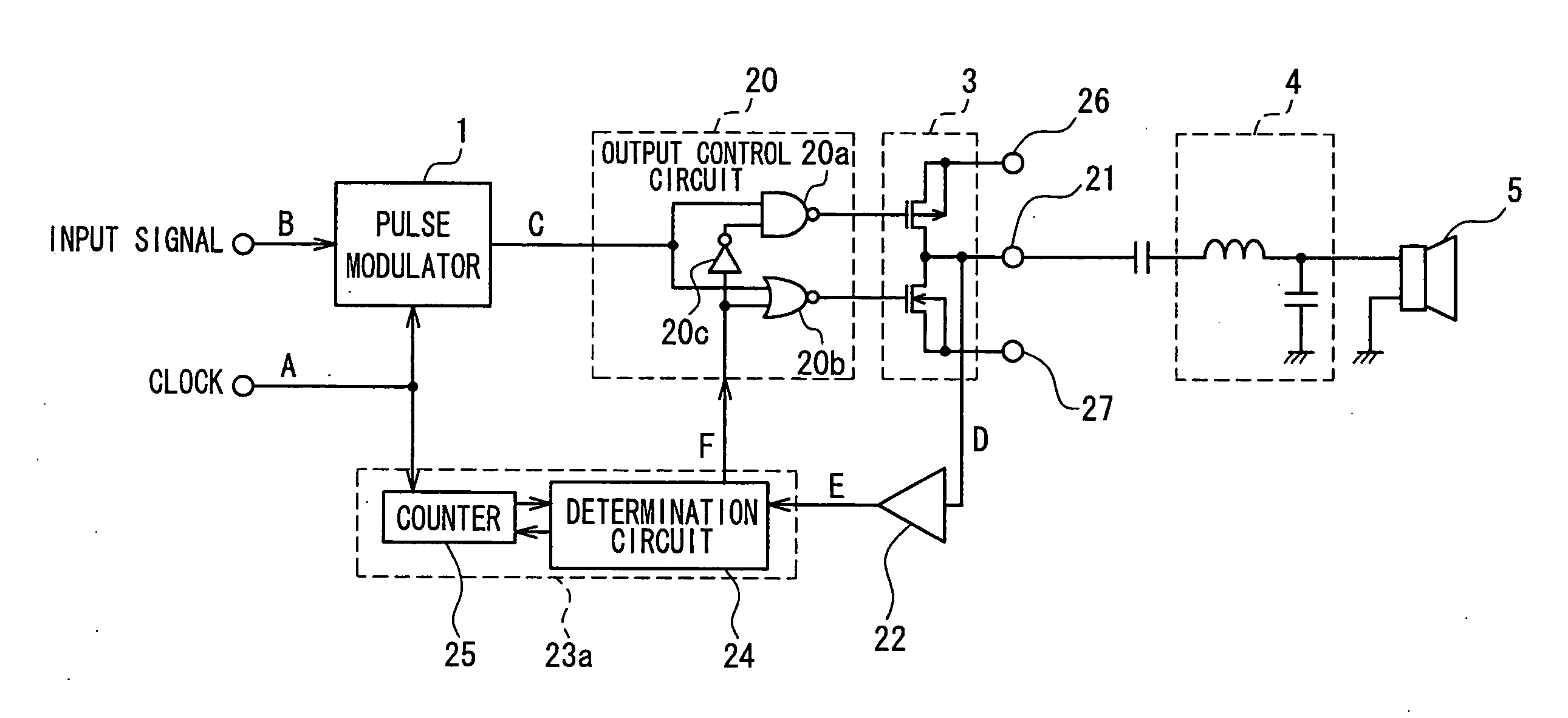
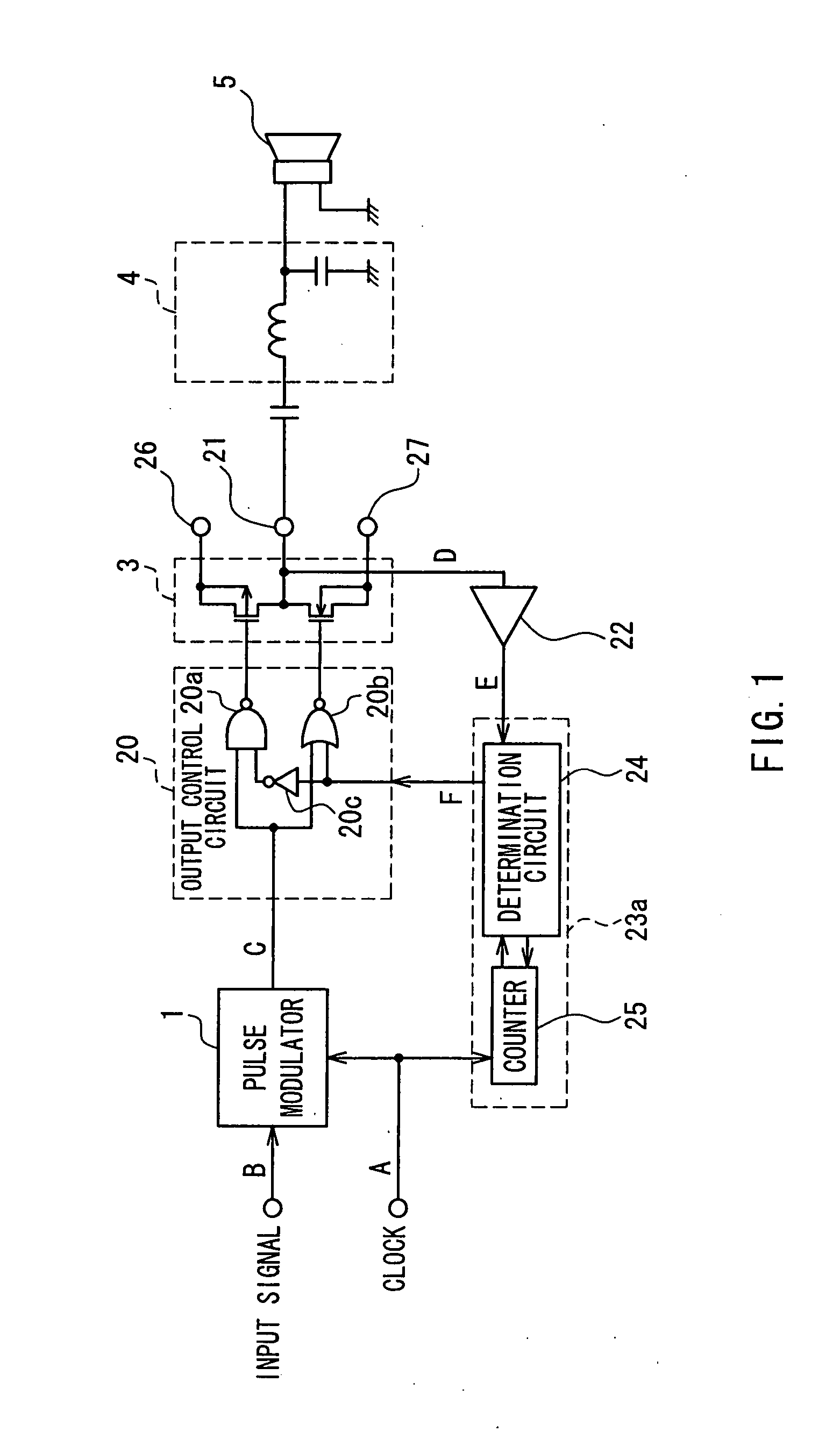
[0051]FIG. 1 is a block diagram showing a pulse modulation type electric power amplifier according to a first embodiment of the present invention. The basic configuration of this circuit is similar to that shown in FIG. 14. The same reference numeral will be attached to like elements, and redundant description will be partly omitted.
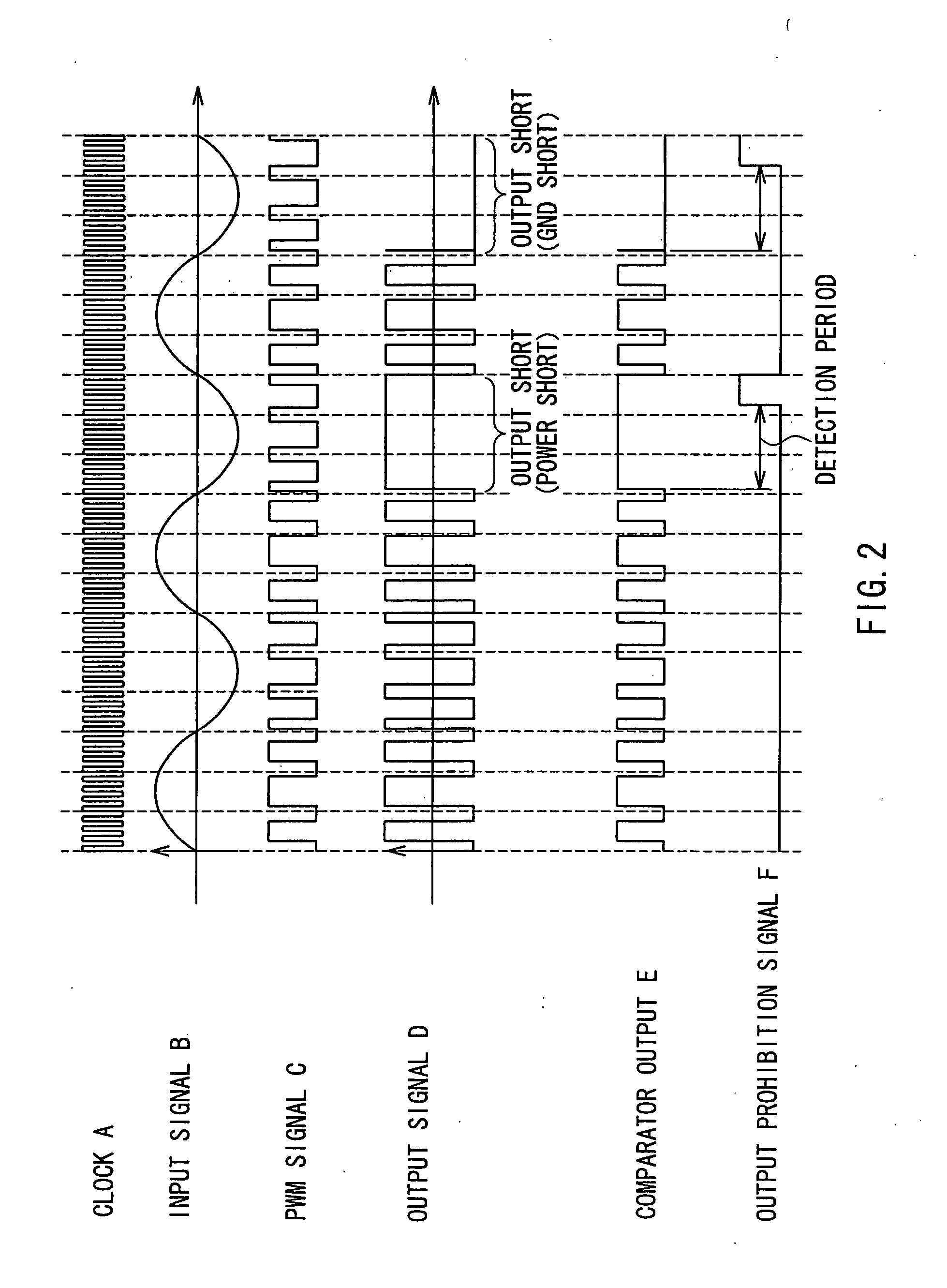
[0052] This pulse modulation type electric power amplifier is basically constituted of a pulse modulator 1 that receives as input a clock A and an analog input signal B, an output control circuit 20 that receives as input an output signal C of the pulse modulator 1 and is configured to be able to stop a switching operation, and an output circuit 3 that performs switching according to the output of the output control circuit 20. Further, a comparator 22 that is connected to an output terminal 21 of the output circuit 3 and a short-circuit determination circuit 23a that is fed with the output of the comparator 22 are provided to constitute protection circ...
second embodiment
[0060]FIG. 3 is a block diagram showing a pulse modulation type electric power amplifier according to a second embodiment of the present invention. This circuit has a configuration in which a short-circuit determination circuit 23b is provided in place of the short-circuit determination circuit 23a in FIG. 1. The short-circuit determination circuit 23b has an EXOR gate 28, with the output E of the comparator 22 being fed as one of the inputs of the EXOR gate 28. The PWM output signal C output from the pulse modulator 1 is fed as the other input of the EXOR gate 28. An output signal G of the EXOR gate 28 is input to the determination circuit 24.
[0061] The operation of this pulse modulation type electric power amplifier is shown in FIG. 4. A to G are the waveforms of the corresponding signals in FIG. 3. The basic operation is similar to the operation of the circuitry in FIG. 1 described with reference to FIG. 2. A difference lies in the operation of the short-circuit determination ci...
third embodiment
[0064]FIG. 5 is a block diagram showing a pulse modulation type electric power amplifier according to a third embodiment of the present invention. The present embodiment relates to a configuration for detecting short circuits between the output terminals of a bridged transformerless (BTL) pulse modulation type electric power amplifier.
[0065] With the circuit in FIG. 5, the output circuit 3 is composed of a first and a second output circuit 3a and 3b having a bridge configuration. PMOS transistor and NMOS transistor pairs of the first and second output circuits 3a and 3b are connected between the power supply terminal 26 and the ground terminal 27, and the connection points of the pairs respectively are connected to a first and a second output terminal 21a and 21b. The output of the first output circuit 3a is differential to the output of the second output circuit 3b.
[0066] An output control circuit 29 has a configuration in which a first and a second output control circuit 29a and...
PUM
 Abstract
Description
Claims
Application Information
 - R&D
- Intellectual Property
- Life Sciences
- Materials
- Tech Scout
- Unparalleled Data Quality
- Higher Quality Content
- 60% Fewer Hallucinations
Browse by: Latest US Patents, China's latest patents, Technical Efficacy Thesaurus, Application Domain, Technology Topic, Popular Technical Reports.
© 2025 PatSnap. All rights reserved.Legal|Privacy policy|Modern Slavery Act Transparency Statement|Sitemap|About US| Contact US: help@patsnap.com


