
Mirror for solid-state laser

a solid-state laser and mirror technology, applied in the direction of laser details, optics, instruments, etc., can solve the problems of accelerating the deterioration of reflectance, hardly achieving reflectance of 99% or more, and affecting the use of the mirror, so as to reduce energy loss due to absorption, improve the reflectance more, and suppress the effect of thermal damage due to light energy absorption

Inactive Publication Date: 2007-10-11
SHIMADZU CORP
View PDF2 Cites 11 Cited by
  • Summary
  • Abstract
  • Description
  • Claims
  • Application Information

AI Technical Summary

Benefits of technology

[0007] In view of the above problems, it is an object of the present invention to provide a mirror for a solid-state laser, capable of achieving higher reflectance than ever before and enhanced durability, particularly when used in a high-power laser apparatus.
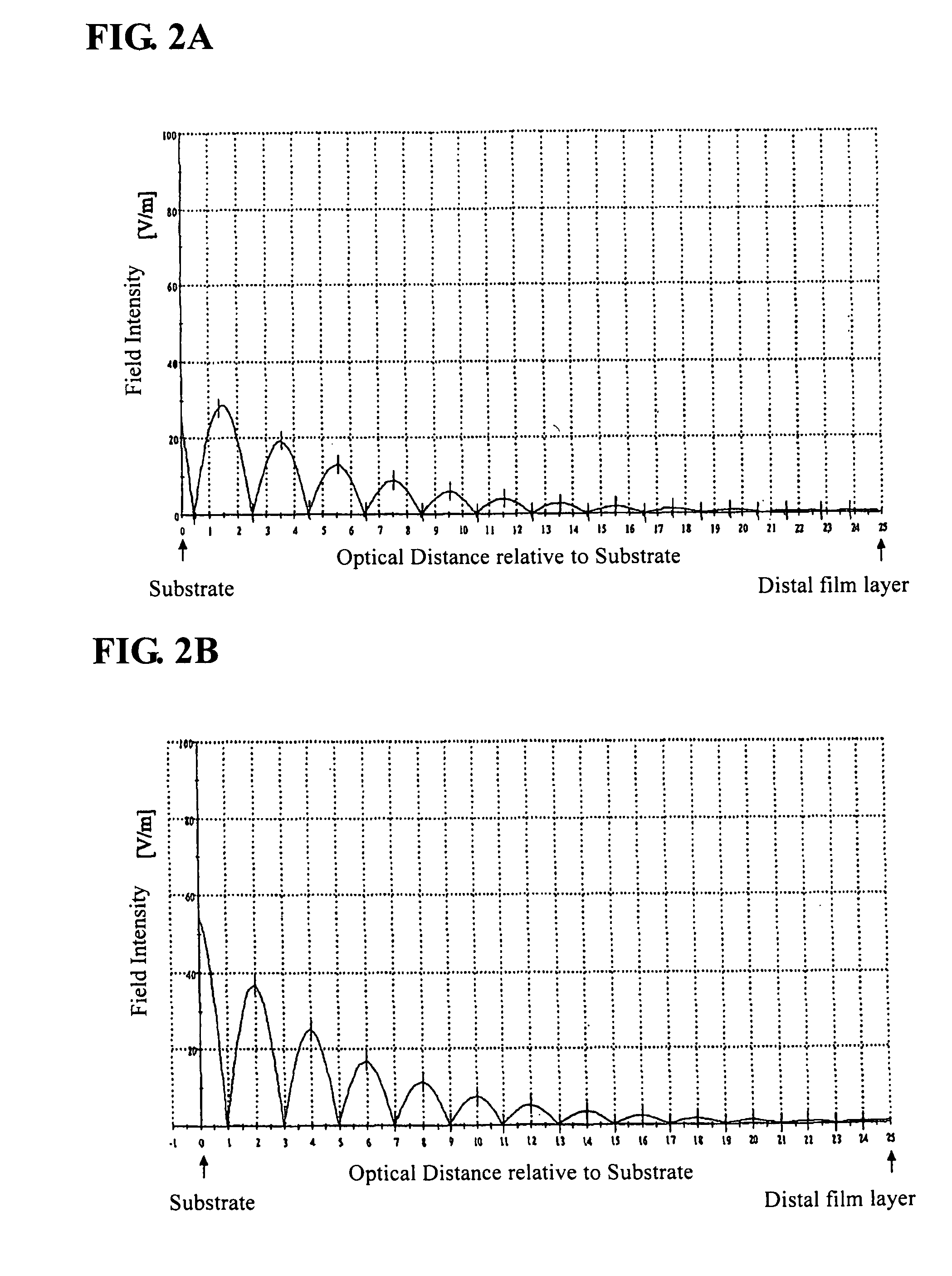
[0014] As above, in the solid-state laser mirror of the present invention, the electric field intensity peak is located in the low-refractive-index film layer, and thereby an energy loss due to absorption can be reduced as compared with a solid-state laser mirror having an electric field intensity peak located in a high low-refractive-index film layer. This makes it possible to improve the reflectance more than ever before so as to get closer to 100%. In addition, thermal damages due to absorption of light energy can be suppressed. This makes it possible to prevent thermal distraction in the film layers so as to achieve enhanced durability even when used in a high-power laser.

Problems solved by technology

Even though the above technique of suppressing light absorption by the film layer and reducing a surface roughness of the film layer the reflectance can be used to increase the reflectance, a reflectance of 99% or more is hardly achieved by simply using such a technique.
Moreover, while no serious problem occurs in a low-power laser, a high-power laser is likely to cause damages (particularly, thermal destruction) of the film layers in the multilayer mirror along with increase in used hours, to accelerate deterioration of the reflectance, resulting in unusable state.

Method used


Image

  • Mirror for solid-state laser
  • Mirror for solid-state laser
  • Mirror for solid-state laser

Examples


Embodiment Construction

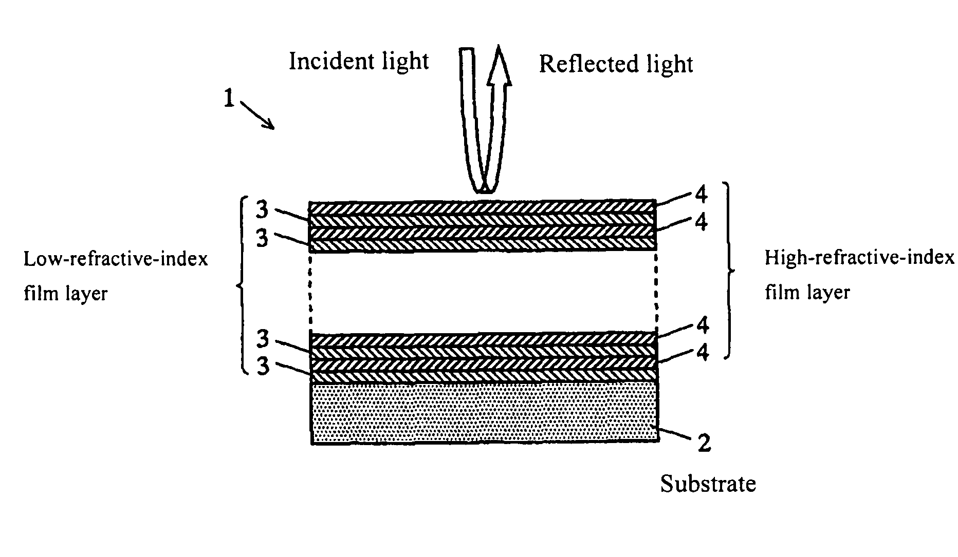
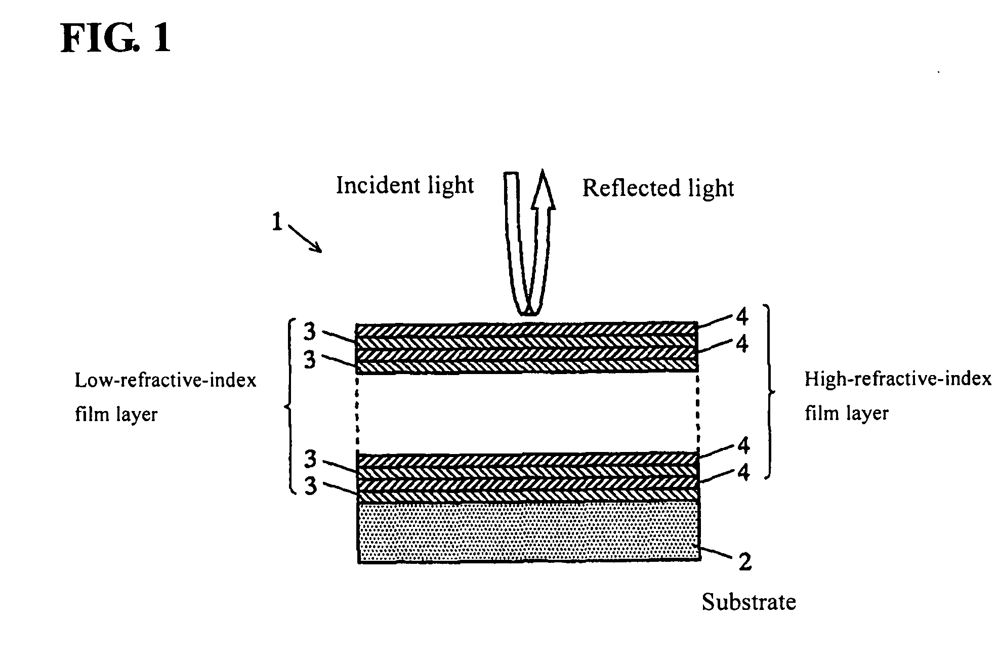
[0017] A solid-state laser multilayer-film mirror according to one embodiment of the present invention will now be described. FIG. 1 is a schematic sectional view of the multilayer-film mirror.

[0018] The multilayer-film mirror 1 comprises a substrate 2 made of synthetic silica and subjected to precision polishing, i.e., polished to have a surface with high flatness, and a multilayer film formed on the substrate 2 by alternately laminating a low-refractive-index film layer 3 made of a dielectric material having relatively low refractive index, and a high-refractive-index film layer 4 made of a dielectric material having a relatively high refractive index. Each of the film layers 3, 4 may be formed using a conventional apparatus for forming a thin film based on a vapor-phase deposition process, such as a resistance heating vapor deposition process, an ion beam process or a sputtering process.

[0019] For example, when the multilayer-film mirror 1 is used in a solid-state laser having ...


PUM


Abstract

A mirror for a solid-state laser, has a multilayer film formed by alternately laminating a low-refractive-index film layer and a high-refractive-index film layer on a substrate. In the mirror, each of the film layers has an optical film-thickness set at a fundamental value in conformity to a wavelength of target light, except that at least one of the film layers has an optical film-thickness adjusted to allow a peak of an electric field intensity distribution formed by repetitive reflections at boundary surfaces between the adjacent film layers to be located in the low-refractive-index film layer.

Description

BACKGROUND OF THE INVENTION [0001] 1. Field of the Invention [0002] The present invention relates to a multilayer-film mirror for use in a solid-state laser, such as LD (laser diode)-pumped YAG (yttrium aluminum garnet) oscillator-based all-solid-state laser, and more particularly to a multilayer-film mirror suitable for use in the deep-ultraviolet range. [0003] 2. Description of the Related Art [0004] A LD-pumped solid-state laser apparatus is designed to generate oscillation using an oscillator defined, for example, between a reflection surface formed at one end of a solid-state laser medium and an output mirror. Heretofore, such an output mirror has been made up of a mirror with a multilayer film structure formed by alternately laminating a high-refractive-index dielectric layer (typically, refractive index: 1.9 or more) and a low-refractive-index dielectric layer (typically, refractive index: 1.5 or less) (see, for example, Japanese Patent Laid-Open Publication No. 05-55671). As...

Claims


Application Information

Patent Timeline
IPC IPC(8): G02B1/10
CPCH01S3/08059G02B5/0833
Inventor TATENO, RYO
Owner SHIMADZU CORP
Learn More