Indirect measurement of negative margin voltages in endurance testing of EEPROM cells

a technology of negative margin voltage and endurance testing, which is applied in the field of memory integrated circuits, can solve the problems of substantial differences in cell behavior and characteristics with respect to one another, and the assumption of program margin symmetry stated supra for an unmeasured threshold voltage of the programmed cell, and achieve the effect of high program margin voltage and endurance or longevity of the cell

Inactive Publication Date: 2007-10-11
ATMEL CORP
View PDF7 Cites 12 Cited by
  • Summary
  • Abstract
  • Description
  • Claims
  • Application Information

AI Technical Summary

Benefits of technology

[0023] Measurement of program margin is important for at least two primary reasons (1) relatively high program margin voltages decrease with time and thus give an initial figure-of-merit or relative health of a memory cell; and, related to the initial figure-of-merit, (2) a higher program margin voltage gives an indication of endurance or longevity of the cell.

Problems solved by technology

With memory array cells already having deep submicron feature sizes, a slight change in processing of one memory cell relative to another during fabrication may result in a substantial difference in a behavior and characteristics of the cells with respect to one another.
However, a typical electrostatic discharge (ESD) protection circuit on a test pad prohibits a negative voltage from being introduced.
If a margin “0” voltage is less than approximately −0.6 volts, a p-n junction of the ESD circuit will be forward biased, potentially causing latchup.
However, an assumption of program margin symmetry stated supra for an unmeasured threshold voltage of the programmed cell may be unjustified.

Method used


Image

  • Indirect measurement of negative margin voltages in endurance testing of EEPROM cells
  • Indirect measurement of negative margin voltages in endurance testing of EEPROM cells
  • Indirect measurement of negative margin voltages in endurance testing of EEPROM cells

Examples


Embodiment Construction

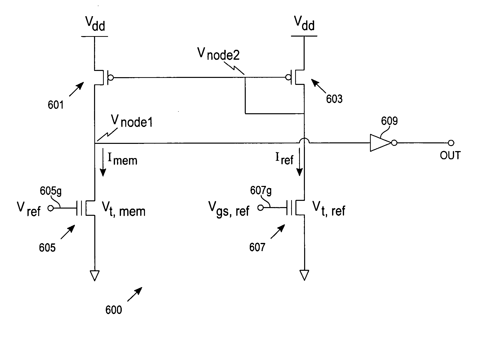
[0033] The present invention provides for indirectly measuring threshold voltages of programmed memory cells (e.g., Flash memory cells), thereby effectively allowing an accurate representation of margin voltages over time for both programmed cells, Vtp, and erased cells, Vte. Calculations presented are for illustrative purposes. Details in regard to mathematical expressions and relationships will vary based on particular circuit configurations or bias conditions that one skilled in the art would readily conceive of in consideration of equivalent situations relative to the present exemplary embodiment.

[0034] With reference to FIG. 4, a block diagram of an exemplary test setup 400 provides a high-level conceptual view of the present invention. The exemplary test setup 400 includes a memory circuit 401, a reference circuit 403, and a comparator 405. An external variable reference voltage is applied to the reference circuit 403 while a fixed positive voltage (e.g., 0.3 volts, not shown...


PUM


Abstract

An electronic test structure and method for testing non-volatile memory cells. The structure includes a first transistor coupled in series to a floating gate transistor whereby a source of the first transistor is coupled to a positive power supply voltage and a source of the floating gate transistor is coupled to a power supply ground. A gate of the first transistor is further coupled to a source of the first transistor. A second transistor is coupled in series with a memory cell with a source of the second transistor coupled to a positive power supply voltage and a gate of the second transistor is coupled to the drain of the first transistor.

Description

TECHNICAL FIELD [0001] The invention generally pertains to memory integrated circuits (ICs). More specifically, the invention is a method and circuit for measuring a threshold voltage of an MOS transistor (e.g., a flash memory cell) having a negative threshold voltage, without a need to supply a negative potential to the gate of the device. BACKGROUND ART [0002] Nonvolatile memory ICs with higher densities are being introduced to the market daily. In order to achieve higher densities, IC manufacturers must continually decrease IC design rules (i.e., rules that state allowable dimensions of features used in the design and layout of integrated circuits). A smaller design rule relates directly to a reduced size of each cell of a memory array. With memory array cells already having deep submicron feature sizes, a slight change in processing of one memory cell relative to another during fabrication may result in a substantial difference in a behavior and characteristics of the cells with...

Claims


Application Information

Patent Timeline
Patent Type & Authority Applications(United States)
IPC IPC(8): G11C7/00
CPCG11C16/04G11C29/50004G11C29/50
Inventor NG, PHILIP S.LE, MINH V.WANG, LIQISON, JINSHU
Owner ATMEL CORP
Why Eureka
Try Eureka