Frequency matched relative position tracking system

a relative position and tracking system technology, applied in direction finders, instruments, computing, etc., can solve the problems of unnecessary phase synchronization between the signal source and the sync clock, and achieve the effects of saving energy, prolonging the transmitter life, and increasing the clocking speed of the microcontroller

a relative position and tracking system technology, applied in direction finders, instruments, computing, etc., can solve the problems of unnecessary phase synchronization between the signal source and the sync clock, and achieve the effects of saving energy, prolonging the transmitter life, and increasing the clocking speed of the microcontroller

US20070237029A1Inactive Publication Date: 2007-10-11HUP

Image

  • Frequency matched relative position tracking system
  • Frequency matched relative position tracking system
  • Frequency matched relative position tracking system

Examples


example 1

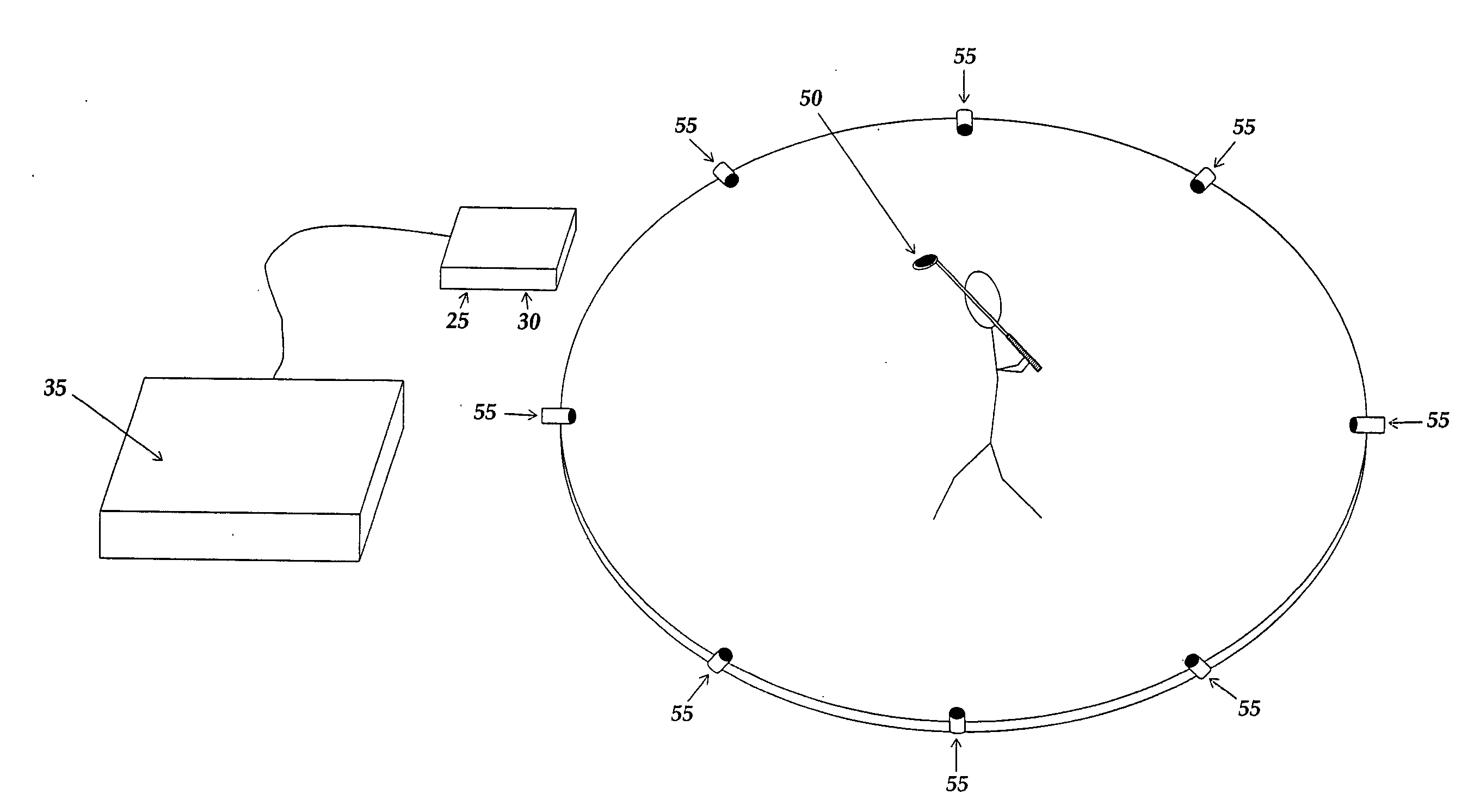
[0042]In one embodiment, the present invention can be used to track the movement of a pointer or writing device for direct input into a computer. As depicted in FIG. 6, an omni directional USS 10 is incorporated into the pointer or writing device 15, and is used in conjunction with two or more ultrasonic transducers 20, an ultrasonic driver 25, and a multi-channel ultrasonic receiver 30 with an RS-232 port (the driver and receiver may be housed together). Although FIG. 1 depicts the pointer 15 as directly connected to the ultrasonic receiver 30 / ultrasonic driver 25, direct connection is not required. The system is also preferably configured to communicate to a central computer 35 (or control system) for processing. The system is also preferably configured to display the tracked movement on a computer display (not depicted).

[0043]If a three-channel three-axis (X-Y-Z) receiver is used, the Z-axis can be assigned a value of 1 due to the two-dimensional application. A communication link...

example 2

[0048]When tracking human movements at a relatively slow speed, such as tracking a pointer or writing implement, a slower sampling rate can be used. However, when tracking fast movement, such as a golf club, bat, or tennis racket, a much higher sampling rate is required.

[0049]For example, in an application using a virtual wavelength of 0.006643 sec. with a frequency of approximately 150 Hz (or cycles per second), and a measuring distance of approximately 7 feet 5 inches, an object traveling at 100 mph can cover that distance in 51 ms. Multiplying the sampling rate by the minimum time it takes an object to cover the measuring distance yields the worst case or minimum number of data points that will be taken (151.9 Hz*51 ms=7.7469) for the given period of time. Obviously 7 data points would be insufficient to accurately track a fast moving object across 7′5″.

[0050]Sixty data points, for example, would work much better for tracking a golf club swing over a 12′ area. An object traveling...


PUM


Abstract

A method and system for relative positional tracking of a signal source is disclosed that requires no phase synchronization between the tracked source and tracking system. A signal source transmits a repeating signal. The virtual wavelength of the repeating signal establishes zones of coverage. The system's sampling rate (or sync clock) corresponds to the frequency of the repeated signal. One or more ultrasonic transceivers placed within the desired coverage area capture the transmitted signal. Before tracking begins, a coordinate system origin (X=0, Y=0, Z=0) is established so that all tracking calculations are relative to the origin. Relative time-of-flight measurements are made by comparing the received signals against a sync clock. Tracking is accomplished by triangulating distance measurements received from the ultrasonic transceivers.

Description

REFERENCE TO RELATED APPLICATIONS[0001]This application claims priority to Provisional Patent Application U.S. Ser. No. 60 / 790,042, entitled “Relative Position Tracking System,” and filed Apr. 7, 2006, which is fully incorporated herein by reference.BACKGROUND OF THE INVENTION[0002]Light, sound, and electromagnetic waves can be used to track an object, with each presenting a unique set of challenges and limiting factors. Ultrasound offers the advantages of low cost, parts availability, established safety record, and license free operation. Light and electromagnetic waves offer the advantage of speed.[0003]Measuring distance to a target is the most fundamental requirement of a tracking system. Using ultrasound to measure distance is straightforward and well documented.[0004]The most common method involves transmitting a short burst of ultrasound towards a target and timing how long it takes for an echo to return. The measured time is proportional to the distance traveled by the sound...

Claims


Application Information

Patent Timeline
11 Oct 2007
Publication
US20070237029A1
IPC
G01S3/80
CPC
G06F3/0433; G01S5/22
Inventors
WATSON, RICHARD