Machine reamer

a technology of machine reamer and reamer blade, which is applied in the direction of manufacturing tools, wood boring tools, transportation and packaging, etc., can solve the problems of difficult high-speed reaming operation, insufficient requirements, and relatively fast wear of the cutting edge of the blade, so as to increase the advantages, and improve the machining performance and durability of the whole of the machine reamer

a technology of machine reamer and reamer blade, which is applied in the direction of manufacturing tools, wood boring tools, transportation and packaging, etc., can solve the problems of difficult high-speed reaming operation, insufficient requirements, and relatively fast wear of the cutting edge of the blade, so as to increase the advantages, and improve the machining performance and durability of the whole of the machine reamer

US20070237593A1Active Publication Date: 2007-10-11YUNITAKKU

Image

  • Machine reamer
  • Machine reamer

Examples


embodiment

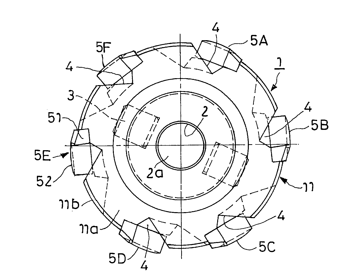
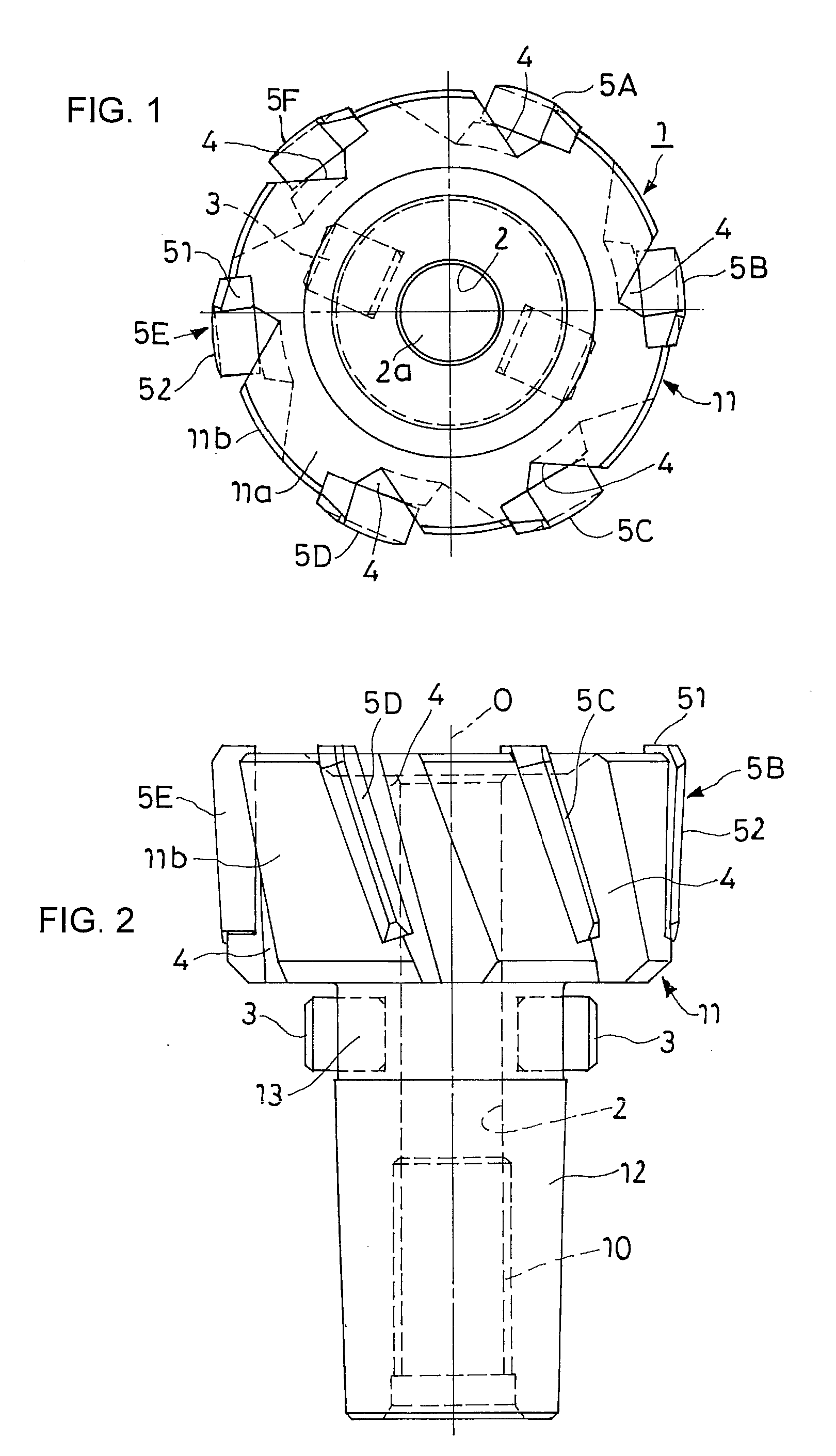
[0039] In the form and the dimensional ratio shown in FIG. 1 and FIG. 2, machine reamers M1 to M7 each of which has six blades 5A to 5F made of materials, respectively, shown in Table 1 presented below were used. Each of the blades 5A to 5F has a tool cutting diameter of 20.0 mm and a length in the axial direction of 13.5 mm. Under the conditions mentioned in the table, a reaming operation was applied to a pilot hole that is 19.5 mm in diameter and that has been pre-bored in a work material of S50C while supplying an oily coolant under a pressure of 5 kg / cm2, so as to examine the cutting speed, the roughness of an inner peripheral surface of the hole, and the heat adhesion degree of the work material. The results are shown in Table 1. The tool materials used for the blades are composed and abbreviated as follows.

Super-hard alloy: WC-based super-hard alloy (ISO-P20)

Ceramic: alumina-based sintered ceramic (85% Al2O3, 3.5% TiC, 10% ZrO3)

Cermet: TiC / N-based cermet [89% (Ti,W)(C,N)...


PUM

PropertyMeasurementUnit
lengthaaaaaaaaaa
cutting diameteraaaaaaaaaa
diameteraaaaaaaaaa

Abstract

A machine reamer has blades to which a work material is not easily adhered by heat even if a cutting speed is increased, and hence high processing efficiency can be obtained. Additionally, the cutting edge of the blade is only slightly worn down even if heavy cutting is performed, and hence excellent durability and an extremely long machine life can be obtained. A plurality of slender blades is erected on the outer peripheral part of a reamer head body. Different kinds of materials are used to make the blades.

Description

RELATED APPLICATIONS [0001] This is a continuation of PCT / JP2006 / 313310, having an international filing date of Jul. 4, 2006, which claims priority from Japanese Application No. JP 2005-214243, filed Jul. 25, 2005.TECHNICAL FIELD [0002] The present invention relates to a machine reamer used to perform a reaming operation after having made holes with a drill. BACKGROUND ART [0003] In general, to adjust the size of a hole of a work material that has been pre-bored with a drill or to smooth the inner peripheral surface of the hole, a reaming operation is performed such that the inner periphery of the hole is cut with a shallow cutting allowance by use of a reamer that is a cutting tool and that has a plurality of slender blades (in most cases, six or eight blades) protruded from the periphery of its head. In recent years, a machine reamer in which blades made of a hard tool material, such as super-hard alloy, ceramic, or cermet, are fixed to, for example, a steel-made reamer head body ...

Claims


Application Information

Patent Timeline
11 Oct 2007
Publication
US20070237593A1
IPC
B23D77/00
CPC
B23D77/02; B23D2277/061; B23D2277/2428; B23D2277/2442; Y10T408/909; B23D2277/2471; B23D2277/34; Y10T408/78
Inventors
NOMURA, TAKUJI