
Method and apparatus defining a color filter array for an image sensor

Inactive Publication Date: 2007-10-11
APTINA IMAGING CORP
View PDF15 Cites 65 Cited by
  • Summary
  • Abstract
  • Description
  • Claims
  • Application Information

AI Technical Summary

Benefits of technology

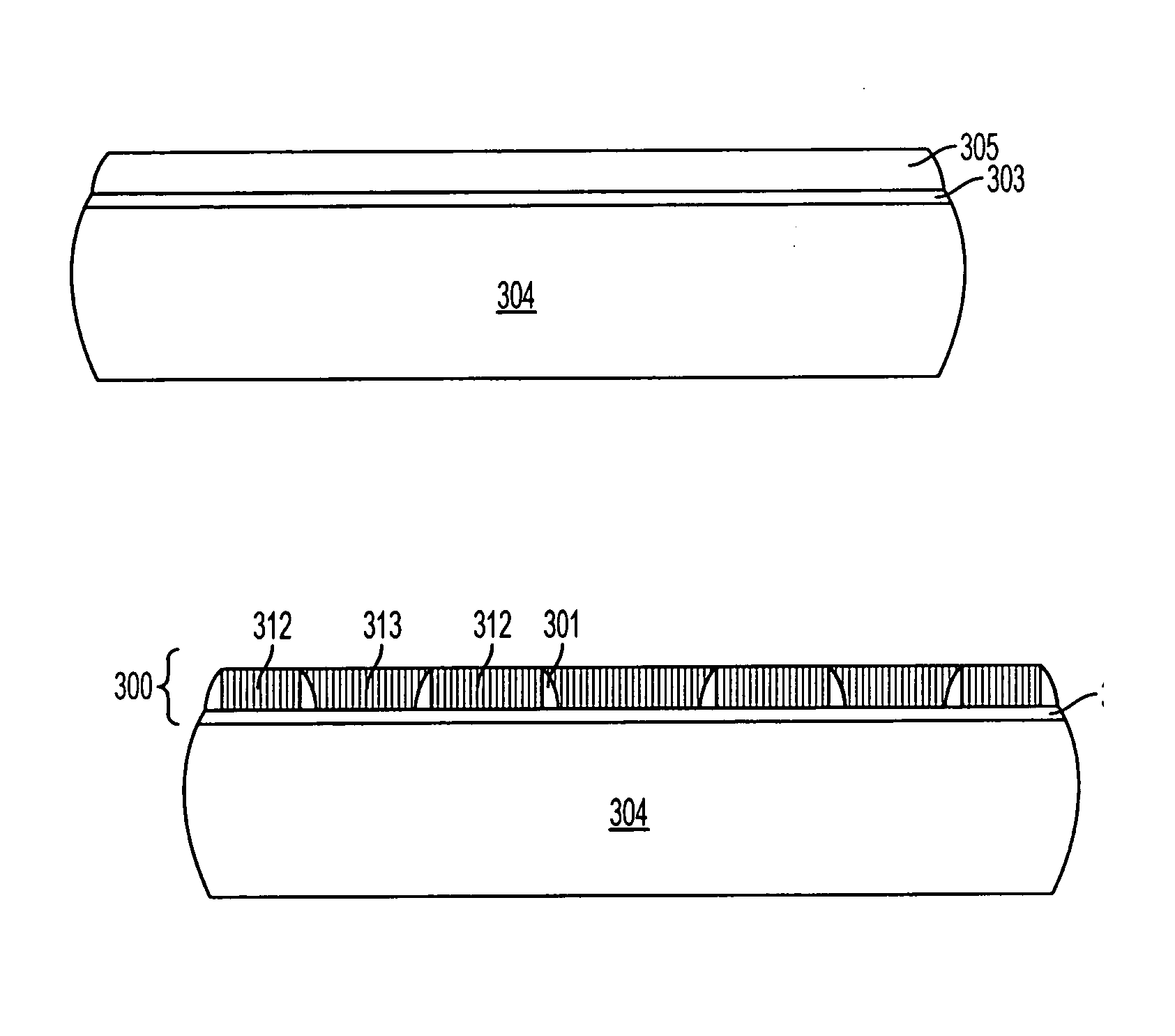
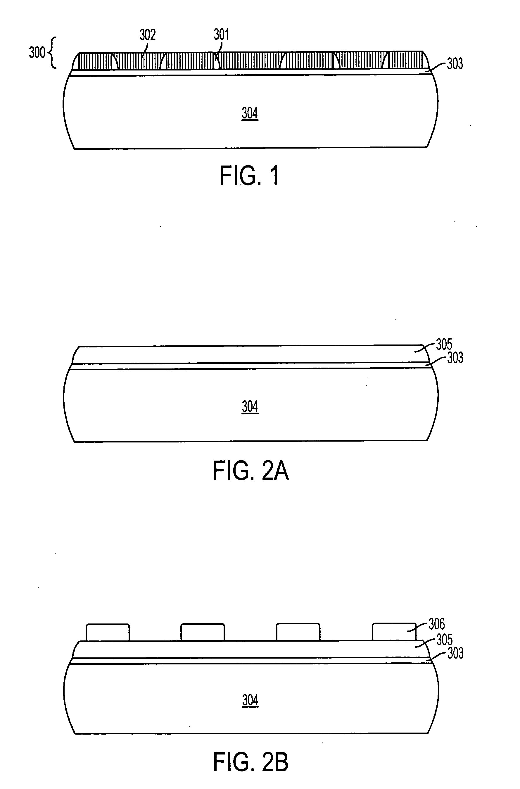
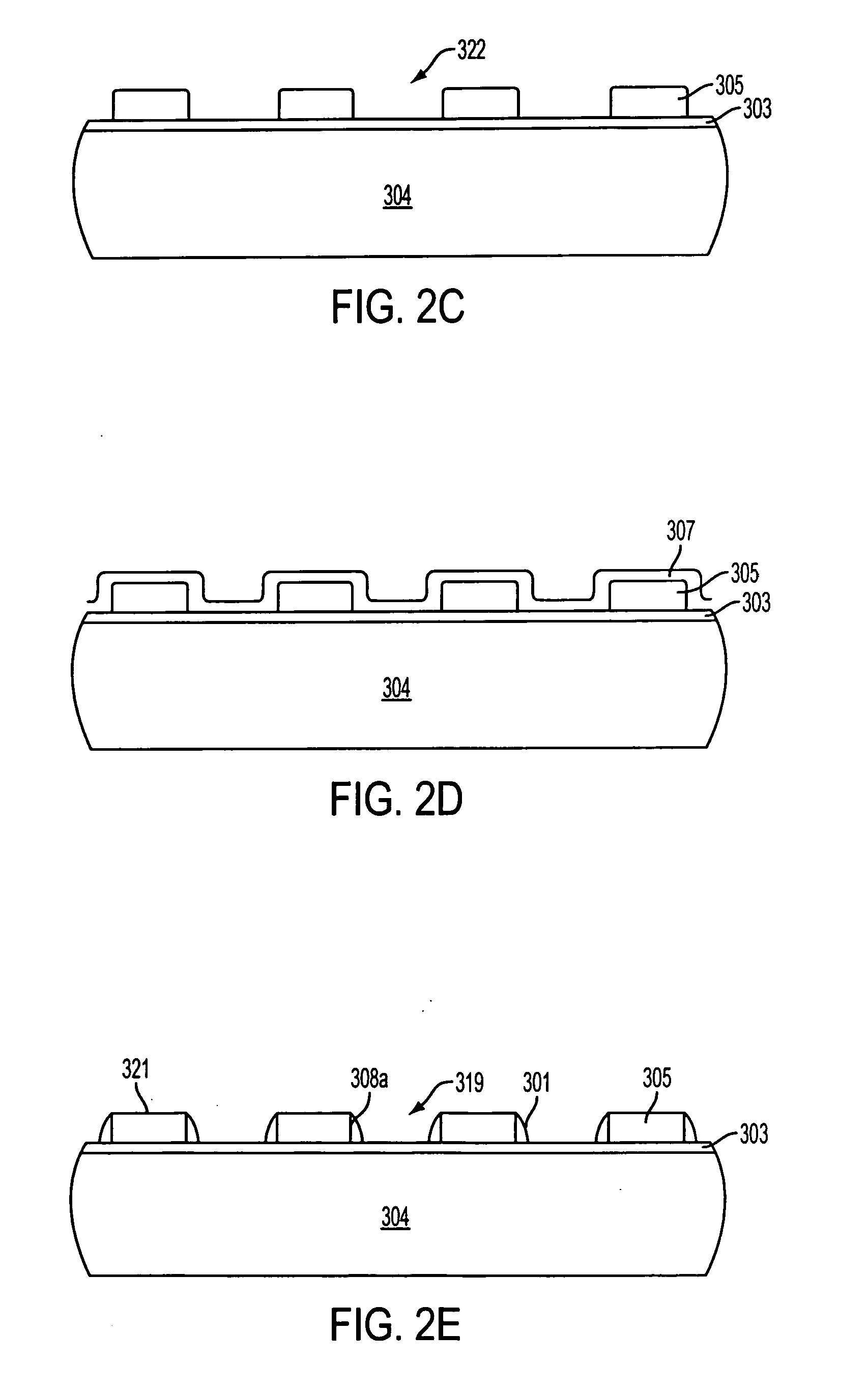
[0011] Exemplary embodiments of the invention provide an imager having an array of color filter elements in which spacers are provided between the color filter elements. The spacers can separate colors from each other (particularly during fabrication) to more accurately define the color filter array colors. In addition, the spacers may be comprised of an opaque material to serve as light blocks surrounding the pixels, thus reducing optical crosstalk between pixels. The spacer material may also serve as a light block covering the periphery circuitry outside a pixel array.
[0012] Also provided are methods of forming a color filter array. In one exemplary method embodiment, a color filter array is produced by forming spacers which define the regions of each color filter element, in order to separate colors and reduce optical crosstalk. The color filter elements are provided in regions defined by the spacers.

Problems solved by technology

However, the negative resist has poor resolution, and suffers from shrinkage and poor planarity which affects the optical properties of the color filter array.
Another disadvantage to this approach is that bonding pads usually are exposed prior to formation of color filter layers.
Thus, chemicals used in the formation of color filter layers can become trapped in the bonding pad area and cause reliability problems and corrode the bonding pad metallization.
In addition, when printing the photoresist, no layer separates the color filter elements from each other to block stray light between pixels, thus resulting in optical crosstalk.

Method used


Image

  • Method and apparatus defining a color filter array for an image sensor
  • Method and apparatus defining a color filter array for an image sensor
  • Method and apparatus defining a color filter array for an image sensor

Examples


Embodiment Construction

[0032] In the following detailed description, reference is made to the accompanying drawings, which form a part hereof and illustrate specific embodiments in which the invention may be practiced. In the drawings, like reference numerals describe substantially similar components throughout the several views. These embodiments are described in sufficient detail to enable those skilled in the art to practice the invention, and it is to be understood that other embodiments may be utilized, and that structural, logical and electrical changes may be made without departing from the spirit and scope of the present invention.

[0033] The term “substrate” is to be understood as including silicon, silicon-on-insulator (SOI), silicon-on-sapphire (SOS), and silicon-on-nothing (SON) technology, doped and undoped semiconductors, epitaxial layers of silicon supported by a base semiconductor foundation, and other semiconductor structures. Furthermore, when reference is made to a “substrate” in the fo...


PUM


Abstract

An apparatus and method to provide an imager having an array of color filter elements, each color filter element being separated from each other by spacers. The spacers can optically isolate filter elements from each other.

Description

FIELD OF THE INVENTION [0001] The present invention relates to color filters for use in a solid-state image sensor and, in particular, to a color filter array having a structure that isolates individual colors from each other, and a method of forming the same. BACKGROUND OF THE INVENTION [0002] Solid-state image sensors, also known as imagers, were developed in the late 1960s and early 1970s primarily for television image acquisition, transmission, and display. An imager absorbs incident radiation of a particular wavelength (such as optical photons, x-rays, or the like) and generates an electrical signal corresponding to the absorbed radiation. There are a number of different types of semiconductor-based imagers, including charge coupled devices (CCDs), photodiode arrays, charge injection devices (CIDs), hybrid focal plan arrays, and CMOS imagers. Current applications of solid-state imagers include cameras, scanners, machine vision systems, vehicle navigation systems, star trackers,...

Claims


Application Information

Patent Timeline
IPC IPC(8): G02B5/20H01L31/0232H01L31/00
CPCH01L27/14621H01L31/02164H01L31/02162H01L27/14623G02B5/20G03F7/40
Inventor HOLSCHER, RICHARD D.BOETTIGER, ULRICH C.
Owner APTINA IMAGING CORP
Learn More